Automatic water filling system
Put a bottle under the tap: the sensor sees it, the timer relay closes, the solenoid valve opens and water runs. After the set time the relay lets go, the valve closes and the water stops.
From the Short Automatic Water Filling System | Solenoid Valve Timer (2.7M views, posted 4 October 2026). Opens on YouTube.
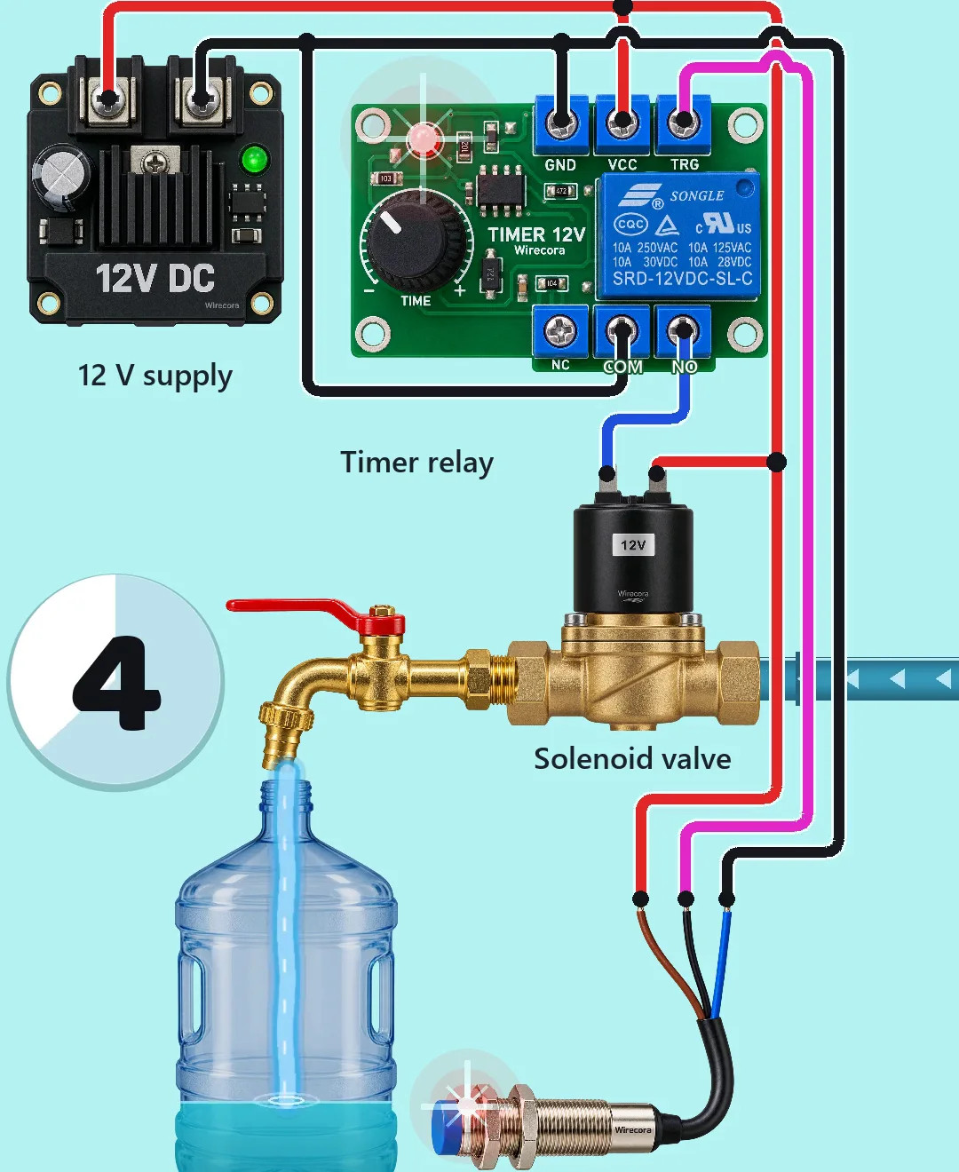
Parts
- 12 V DC power supply module
- 12 V one-shot delay timer relay module (a trimmer sets the time; the relay contacts are rated 10 A at 30 V DC)
- Capacitive proximity sensor, 12 V, three wires, NPN normally open (for example LJC18A3-H-Z/BX). It must be capacitive: an inductive sensor (the metal-barrel LJ12A3 type) sees only metal and misses a plastic bottle
- 1N4007 diode across the solenoid coil
- 12 V solenoid valve, normally closed, with a brass tap on its outlet
- A bottle, hose and the water supply
How it is wired
- Supply plus (red) to the timer's VCC, the sensor's brown wire, and one terminal of the solenoid coil.
- Supply minus (black) to the timer's GND, the sensor's blue wire, and the timer's COM contact.
- Sensor black wire (its output) to the timer's TRG. The output pulls down to minus while a bottle is in front of the sensor.
- Timer NO contact to the other terminal of the solenoid coil. The coil has no plus or minus side.
- 1N4007 across the coil: its band (cathode) on the coil terminal joined to supply plus, the other end on the terminal joined to the NO contact. It catches the voltage kick when the coil switches off and saves the relay contacts.
How it works
- With no bottle, the sensor's output is open, the relay is off, the NO contact is open and the valve stays closed.
- A bottle in front of the sensor pulls TRG down to minus. The timer sees that falling edge and pulls its relay in for the time set on the trimmer.
- The closed NO contact joins the coil's second terminal to minus, so the coil sees the full 12 V and the valve opens.
- When the time is up the relay lets go, the coil loses its 12 V and the valve closes. The timer does not start again while the same bottle stands there; it waits for the next bottle.
What the video simplifies
- The Short fills a 20 litre bottle in 3.5 seconds. A real one takes minutes, so the trimmer would be set to minutes, not seconds.
- The countdown disc and the word STOP are graphics in the video, not parts of the circuit.
- No fuse is drawn. Put one in the 12 V plus lead of a real build.
- The sensing distance in the video is made up; read the real one on the sensor's label. A capacitive sensor reaches a few millimetres to about 1 cm through a thin plastic wall, so mount its face close to the bottle and set its trimmer.
- The sensor drawn in the Short looks like a metal-barrel inductive sensor. That type would not see a plastic bottle; build it with a capacitive one as listed here (viewers rightly pointed this out).
- A timer fills by time, not by level, so the amount changes with the water pressure. For an exact level, add a second capacitive sensor at the fill line that stops the valve, and keep the timer as a safety limit.
Everything here runs on 12 V DC. Keep the supply module dry and above the water, and never wire a mains solenoid or timer this way.
Build it yourself
The wiring board has no timer relay module yet, so this one cannot be opened on it. Start with the guided first build on the wiring board, where a circuit really works as you wire it, then try the ready-made ones.
Your first circuit, step by stepAll circuits from the Shorts
Stuck, or built it?
Ask about this circuit or show your build in the Wirecora Discord. Questions get an answer every day.