Automatic water tap
Hold your hands under the tap: the IR sensor sees them, the relay clicks and water pours onto your hands. Take your hands away and the relay clicks off and the water stops.
From the Short Automatic Water Tap Circuit | IR Sensor + Solenoid Valve (264K views, posted 30 September 2026). Opens on YouTube.
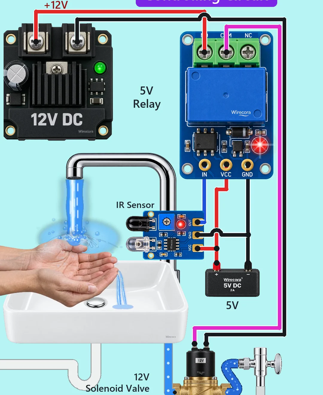
Parts
- IR obstacle sensor module, 5 V, pads VCC, GND and OUT (it has its own LM393 comparator; OUT goes LOW when it sees something)
- 5 V relay module, low-level trigger, pads IN, VCC and GND, contacts NO, COM and NC (contacts rated 10 A at 30 V DC; coil about 70 mA)
- 12 V solenoid valve, normally closed, two terminals (the coil has no plus or minus side; about 0.5 A for a typical 6 W valve, check yours)
- 12 V DC supply module (at least 1 A)
- 5 V DC supply module
- 1N4007 diode across the valve coil. It is recommended and is not drawn in the Short.
- A tap, a basin, a stop valve, pipes and the water supply
How it is wired
- 5 V supply plus to the relay's VCC and the sensor's VCC.
- 5 V supply minus to the relay's GND and the sensor's GND.
- Sensor OUT to the relay's IN, and to nothing else.
- 12 V supply plus to the relay's NO contact.
- Relay COM contact to one terminal of the solenoid valve.
- The valve's other terminal to the 12 V supply minus.
- Relay NC contact is left unconnected.
- Not drawn in the Short, but add it: the 1N4007 across the valve's two terminals, band (cathode) on the side wired to COM, the other end on the side wired to 12 V minus.
How it works
- The IR sensor shines invisible light forward. When your hands are close they bounce it back, and the sensor's comparator pulls OUT down to LOW. With no hands, a 10 k pull-up on the module holds OUT HIGH at 5 V.
- The relay module switches on when its IN pin is pulled LOW, so OUT can be wired straight to IN. A LOW sensor output turns the relay on and its NO contact closes. The sensor only has to sink about 4 mA for this (a typical figure for these relay boards), and its LM393 can sink at least 6 mA.
- The closed contact joins 12 V plus through COM to the valve, so the valve's coil gets 12 V and the valve opens. Water flows for as long as your hands stay there.
- Take your hands away: OUT goes HIGH, the relay lets go, the valve loses its 12 V and closes, and the water stops.
- The 12 V valve side and the 5 V sensor side share no wire and no ground. The relay contacts are the only link between them.
What the video simplifies
- The water stream, the splash, the drops and the puddle are drawn for the video.
- The short delays between the relay click, the valve and the water at the spout are made up for the video.
- The pipe after the valve turns blue only while water flows. A real pipe stays full of water after the valve closes.
- The hands' washing motion is animation, and the sensing distance is only for show: a real module's range is a few centimetres and is set with its trimmer.
- The relay and sensor indicator LEDs are switched on and off in the picture to show their state.
- The original video used mains wiring. This one uses ready 12 V and 5 V supply modules, and no mains is shown.
- No diode is drawn across the valve coil. Fit a 1N4007 in a real build: without it the coil's kick when it switches off makes the relay contacts spark and wear out sooner.
- The sound is synthesised.
Everything runs on 12 V and 5 V DC; keep the supply modules and the circuit dry and above the water, use a valve rated for your water pressure, and keep mains wiring out of it.
Build it yourself
The wiring board has this whole circuit, the diode included, as its ready-made Touchless tap: open the wiring board and pick Touchless tap to play with it. Start with the guided first build on the wiring board, where a circuit really works as you wire it, then try the ready-made ones.
Your first circuit, step by stepAll circuits from the Shorts
Stuck, or built it?
Ask about this circuit or show your build in the Wirecora Discord. Questions get an answer every day.