18650 charger with a full indicator
The charger is plugged in and the holder is empty, so the green Full LED is already lit. Drop an 18650 cell into the holder and the green LED goes out, the red Charging LED comes on and a counter climbs. When the cell is full the red LED goes out and the green Full LED lights again. Lift the cell out and the green LED stays on.
From the Short 18650 Charger Circuit with Full Indicator (TP4056) (266K views, posted 9 October 2026). Opens on YouTube.
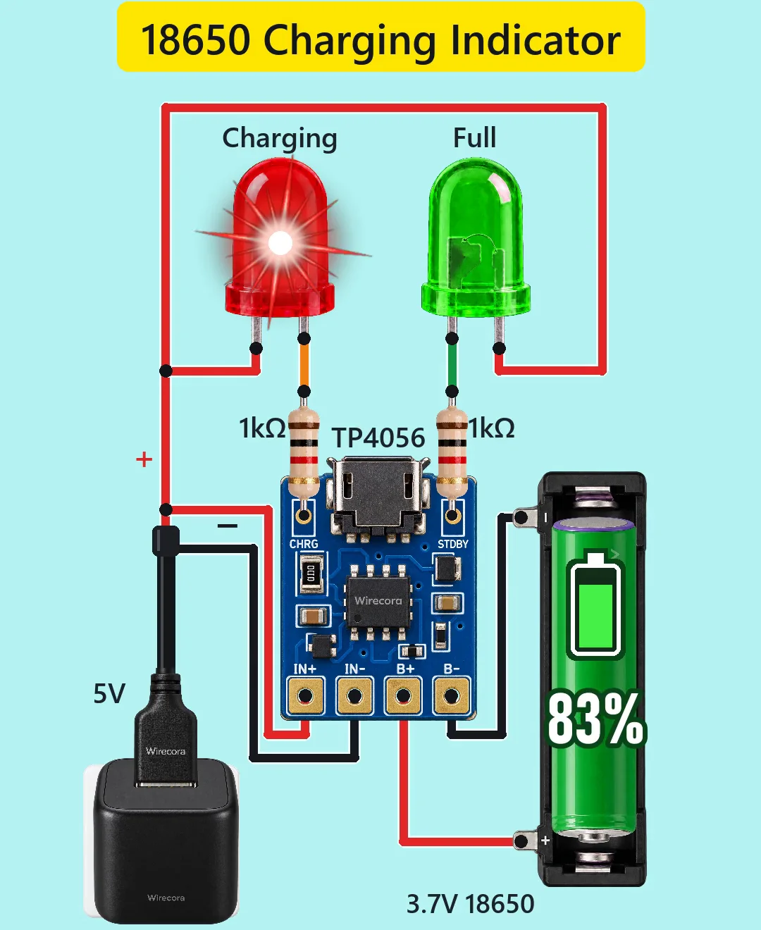
Parts
- TP4056 charger module (the common blue board: TP4056 chip, 1.2 k PROG resistor, TEMP tied to ground, 10 uF on the input and the battery side; its own micro-USB socket is not used)
- Red 5 mm LED (Charging)
- Green 5 mm LED (Full)
- Two 1 k resistors, 1/4 W, one in each LED branch
- 18650 Li-ion cell, 3.7 V (4.2 V full), about 3000 mAh, protected, in a single-cell holder
- 5 V USB phone charger that can give at least 1 A (a 5 V 2 A one), with a short, thick USB cable cut open: red is +5 V, black is ground. The white and green data wires are not used. A 500 mA computer USB port is not enough for this module.
How it is wired
- USB red (+5 V) to the module's IN+, to the red LED's anode (long leg) and to the green LED's anode.
- USB black (ground) to the module's IN-.
- Red LED cathode (short leg) to one 1 k resistor; the other end of that resistor to the module's CHRG pad.
- Green LED cathode to the other 1 k resistor; the other end of that resistor to the module's STDBY pad.
- Cell plus to the module's B+.
- Cell minus to the module's B-. On the real module B- and IN- are the same copper.
How it works
- The TP4056 is a charger chip for one lithium cell. It gives the cell a steady current, then holds 4.2 V and lets the current fall. With the 1.2 k PROG resistor that steady current is about 0.9 to 1 A, so it suits cells of 2000 mAh and up and needs a charger that can give at least 1 A through a short, thick cable (a thin cable drops too much voltage and the chip cannot reach full current). A very flat cell, under 2.9 V, first gets a small current of about 120 mA until it recovers.
- While it is charging, the chip pulls its CHRG pin low (to about 0.2 V). The red LED, through its 1 k resistor, gets a path from +5 V to that pin and lights with about 2.8 mA.
- When the charge current has fallen to about one tenth (about 120 mA) at 4.2 V, the chip lets CHRG go and pulls STDBY low instead. The red LED goes dark and the green LED lights.
- With no cell in the holder the chip also pulls STDBY low, so the green LED is on before the cell goes in and after it comes out. That is why green does not always mean full.
- The chip is a linear charger: the difference between 5 V and the cell voltage, times the current, becomes heat. With a flat cell at 1 A that is up to about 2 W, so the chip gets hot and cuts the current back, and a real module often charges a little under 1 A. A real charge of a 3000 mAh cell takes about 3 hours.
What the video simplifies
- The charge takes about 3 hours in real life and 3 seconds in the Short. The percent counter and its rhythm are a graphic; the chip does not report a percentage.
- The bright pulses running along the B+ wire, the LED flares and the click are animation.
- The stock module has two small LEDs on the board. The Short draws them as separate LEDs soldered to the CHRG and STDBY pads; wire yours the same way. On a stock module its own two small LEDs stay in the circuit and light together with yours.
- The USB cable is cut open to reach IN+ and IN-; the module's own micro-USB socket is not used.
- With no cell in the holder the real chip also makes the red LED flicker once every 1 to 4 seconds. That flicker is not drawn.
- The plain module has no cell protection: use a protected 18650, or the module version with the DW01 protection chip.
Everything runs on 5 V, but the charger chip gets hot at 1 A and a lithium cell can be dangerous if charged the wrong way round or shorted, so keep the module in the open air, check the cell's plus and minus before it goes in, use a protected cell of 2000 mAh or more, and never leave a charging cell on a flammable surface.
Build it yourself
The wiring board has no TP4056 charger module or lithium cell yet, so this one cannot be opened on it. Start with the guided first build on the wiring board, where a circuit really works as you wire it, then try the ready-made ones.
Your first circuit, step by stepAll circuits from the Shorts
Stuck, or built it?
Ask about this circuit or show your build in the Wirecora Discord. Questions get an answer every day.