12 V bike indicator flasher with a 555
Hold the toggle to the left and the left lamp flashes amber about twice a second for as long as you hold it (three flashes in the clip). Hold it to the right and the right lamp flashes. Let go and the lever springs back to the middle, so both lamps stay dark.
From the Short 12V Bike Indicator Flasher Circuit | NE555 (229K views, posted 2026). Opens on YouTube.
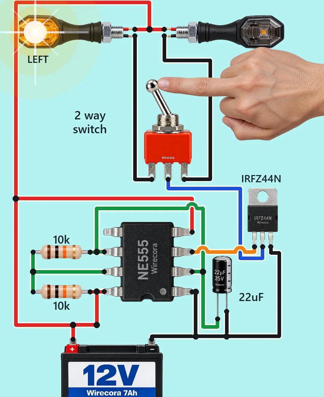
Parts
- NE555 timer, DIP-8
- Two 10 k resistors (R1 and R2)
- 22 uF electrolytic capacitor (mind the polarity; pick one rated above 12 V, a 25 V part is the usual choice)
- IRFZ44N MOSFET, TO-220 (printed face towards you, metal tab at the back, legs down: G, D, S from the left; rated 55 V, 49 A)
- Toggle switch, ON-OFF-ON with spring return to the middle (the "2 way switch" in the video)
- Two 12 V 3 W LED-type motorcycle indicator lamps (about 0.25 A each)
- 12 V motorcycle battery
How it is wired
- Battery plus (+12 V) to 555 pin 8 (VCC) and pin 4 (RESET), to the top of R1, and to the plus terminal of both lamps.
- Battery minus to 555 pin 1 (GND), to the capacitor's minus leg, and to the IRFZ44N source.
- R1 from +12 V to 555 pin 7 (DISCH); R2 from pin 7 to pins 6 and 2 (THRES and TRIG), which are tied together.
- Capacitor plus leg to pins 6 and 2; its minus leg to ground. Pin 5 (CTRL) is left open.
- 555 pin 3 (OUT) to the IRFZ44N gate.
- IRFZ44N drain (the middle leg, joined to the tab) to the centre lug of the toggle switch.
- Left lamp minus terminal to one outer lug of the toggle; right lamp minus terminal to the other outer lug.
How it works
- The 555 runs free (an astable): the capacitor charges through R1 and R2 and empties through R2 into pin 7, so pin 3 goes high and low on its own, about 2.2 times a second (high 0.31 s, low 0.15 s with these values).
- When pin 3 is high it puts about 10 V on the MOSFET gate, well above the 2 to 4 V the IRFZ44N needs to start conducting, so the MOSFET switches fully on and joins the switch's centre lug to ground.
- The toggle picks which lamp's minus terminal is joined to that centre lug. That lamp then sees 12 V and lights; when pin 3 goes low the MOSFET turns off and the lamp goes dark.
- With the lever in the middle no lamp is connected, so nothing flashes even though the 555 keeps running.
- Each lamp draws about 0.25 A, far below what the IRFZ44N can carry, and the 555 only drives the gate, so it never carries the lamp current (its own output limit is about 200 mA).
What the video simplifies
- The three flashes per push in the video come from holding the lever for about 1.4 s and letting go; the 555 just free-runs, it does not count flashes.
- The lever springing back, the lamp flare and all the sounds are made for the video.
- A gate resistor of about 100 ohm and a 10 k gate pull-down are not drawn; use them in a real build.
- Pin 5 is left open; a 10 nF capacitor from pin 5 to ground is optional.
All 12 V DC from the bike battery; on a real bike put a fuse in the plus lead, and a 12 V battery can push a lot of current into a short, so keep the wires tidy.
Build it yourself
The wiring board has no 555 or capacitor yet, so this one cannot be opened on it. Start with the guided first build on the wiring board, where a circuit really works as you wire it, then try the ready-made ones.
Your first circuit, step by stepAll circuits from the Shorts
Stuck, or built it?
Ask about this circuit or show your build in the Wirecora Discord. Questions get an answer every day.