Driveway candy launcher with an HC-SR04, two flywheels, a servo and an Arduino Nano
A trick-or-treater at the curb holds up a bucket. The sensor on the launcher's post sees it closer than 150 cm, two small flywheels whir up, and a servo pushes one wrapped chew at a time into them: two chews lob up and drop into the bucket, about 1.2 m away. Then the wheels coast down, and it fires again only after nothing has been in front of it for 2 seconds, so each bucket gets one pair.
From the Short Raise Your Bucket and the Driveway Launcher Lobs Candy In (posted 26 October 2026). Opens on YouTube.
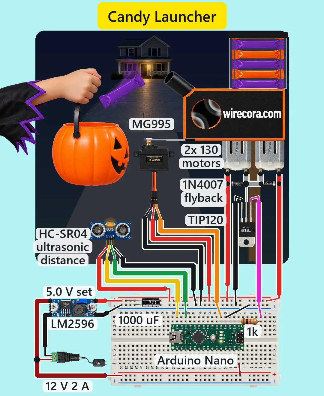
Parts
- Arduino Nano (an Uno works the same: same chip, same pins, same sketch)
- HC-SR04 ultrasonic sensor, 5 V, about 15 mA, pins VCC, TRIG, ECHO, GND
- MG995 servo for the pusher (brown GND, red VCC, orange signal; 4.8 to 7.2 V; about 1.5 A when stalled)
- Two 130 size DC motors (rated 6 V, about 70 mA with no load, 0.5 A stalled), each with a 40 mm flywheel with a rubber tyre
- TIP120 Darlington transistor (face towards you, legs down: B, C, E from the left; the metal tab is the collector)
- 1k resistor for the TIP120 base (bands brown, black, red, gold)
- Two 1N4007 diodes, one flyback diode across each motor (the band is the cathode)
- 1000 uF 25 V electrolytic capacitor (the stripe is the minus side)
- LM2596 buck converter module (3.5 to 40 V in, about 1.5 A continuous out), set to 5.0 V
- 12 V 2 A adapter, centre positive, and a DC barrel jack with screw terminals
- Half breadboard and jumper wires
- The launcher: a head with the two wheels side by side and a short barrel pointing up at about 37 degrees, a one-chew-wide magazine above the wheels, a chute that drops the lowest chew in front of the pusher, and a post to mount it at the curb
- Light, soft wrapped chews of about 5 g (taffy-style sticks). Heavier candy such as a 17 g fun-size bar leaves at about half the speed and falls short.
How it is wired
- Adapter into the barrel jack. Jack + (12 V) to the LM2596 IN+ and to the breadboard's bottom + rail; a jumper from that rail to the Nano's VIN pin (made for 7 to 12 V). Jack minus to the LM2596 IN-.
- Before anything else is connected, power the LM2596 and turn its trimmer until a meter reads 5.0 V between OUT+ and OUT-. A new module can give about 11 V, which would kill the servo and the sensor.
- LM2596 OUT+ to the breadboard's top + rail (5 V) and OUT- to the top minus rail (GND). The bottom + rail carries 12 V: mark it so nothing 5 V goes there. The Nano's 5V pin stays empty.
- The 1000 uF across the 5 V rail: long leg on +5 V, stripe leg on GND.
- HC-SR04: VCC to +5 V, GND to GND, TRIG to Nano D12, ECHO to Nano D10.
- MG995: red to +5 V, brown to GND, orange (signal) to Nano D2.
- Nano D3 to the 1k; the other end of the 1k to the TIP120 base (B). TIP120 emitter (E) to GND.
- Motor 1: one lead to +5 V, the other to the TIP120 collector (C). Motor 2 the same, but with its leads the other way round, so the two wheels spin in opposite directions and both push the chew out of the barrel.
- A 1N4007 across each motor: band (cathode) on the +5 V lead, plain end on the lead that goes to the TIP120 collector.
- A Nano GND pin to the GND rail. One common ground for the jack, the LM2596, the Nano, the sensor, the servo and the TIP120.
- Mount the sensor on the post at bucket height, looking out at where a kid holds the bucket. Aim the barrel so the chews land about 1.2 m out, with the bucket's mouth about 40 cm below the muzzle.
- Set the wheel gap a little narrower than a chew is thick, so both tyres grip it. Fit the servo horn so write(20) holds the pusher clear of the chute and write(60) pushes the chew into the wheels (about 14 mm of travel on a 20 mm horn).
How it works
- The Nano pings the HC-SR04 about 11 times a second while nothing is near and about 15 times a second with something near. Echo time in microseconds divided by 58 is the distance in cm; no echo within 30 ms counts as nothing there.
- A reading under 150 cm fires. The sketch puts the wheels on full power for a short burst, longer for a farther bucket (167 ms at 50 cm to 333 ms at 150 cm), then holds them at a PWM speed set by the distance (duty 63 to 111 of 255): a nearer bucket gets a softer throw.
- For a bucket at about 1 m: 250 ms at full power, then duty 87 (34 %). The wheels reach about 222 rad/s (2,100 rpm), a rim speed of 4.4 m/s.
- The servo moves the pusher to 60 degrees for 150 ms, which slides the lowest chew into the wheels, then back to 20 degrees so the next chew drops into place. The barrel points up, so gravity cannot feed the wheels: the pusher has to.
- Light chews only: the spinning wheels act like a 10 g mass at the rim, so a 5 g chew leaves at 10/15 of the rim speed, about 3.0 m/s (11 km/h). At about 37 degrees it lands 0.5 s later, about 1.2 m out. The wheels lose a third of their speed at each grip and win most of it back in the 1.1 s before the second chew, which leaves at about 2.8 m/s and lands about 10 cm shorter, still inside a 16 cm bucket mouth.
- After the second chew the wheels switch off and coast to a stop in about a second. The flyback diodes take each motor's current when the TIP120 switches off (every PWM pulse and at the end), so no voltage spike reaches the transistor; they carry at most 0.34 A of their 1 A.
- Then it waits until nothing has been under 150 cm for 2 s. A kid who keeps holding the bucket up gets no more until they lower it or step back. The sensor is not read while the wheels are powered or the pusher moves, and a reading during the 2 s wait (while the wheels coast and the last chew is still in the air) only restarts the wait, so motor noise or a chew in flight cannot fire a second throw.
- The TIP120 drops about 0.9 V, so the motors get about 4.1 V: each draws up to 0.34 A when starting. Its base gets (5 - 1.4) / 1k = 3.6 mA from D3, five times the 0.7 mA it needs to pass 0.68 A.
- Heat: at most 0.68 A x about 1 V = 0.7 W in the TIP120, at the start or with a jammed chew, and the sketch switches the wheels off within 2 s after every trip. It takes 2 W in free air, so it needs no heatsink.
- Currents: both motors starting take 0.68 A of the LM2596's 1.5 A. The worst jam (wheels and pusher stalled for 0.15 s) is about 2.2 A for that moment, and the adapter gives about 1.1 A of its 2 A at worst, about 0.4 A on a normal throw. The Nano runs from 12 V on its own regulator, which loses about 0.16 W.
- Pins: the Servo library takes Timer1, which only stops PWM on D9 and D10; D10 works normally as the ECHO input, and the wheels' PWM on D3 runs on Timer2 at 490 Hz.
- The distance table is worked out in a model so both chews land in a 16 cm bucket mouth from 50 to 150 cm (worst miss 7.7 cm from the centre). Real motor friction makes the wheels hold faster than the model, so treat the two map lines as a starting point and tune them with a few test throws.
The code: candy_launcher.ino
The Arduino code for this circuit is in the Wirecora Discord, in the channel #arduino-code (owner’s choice, 14 October 2026: the code lives where you can ask about it). It is a plain .ino file you can download there.
The sketch the Short was animated from: its timing ran step by step in the video's simulation against the drawn bucket. It uses the Servo library that comes with the Arduino IDE. It has not been run on a real board. Tune the two map lines with a few test throws: if the chews fall short, raise the numbers; if they fly past, lower them. If the pusher does not reach the wheels or hits the chute, change PUSH and BACK.
What the video simplifies
- The bucket is drawn much nearer than its real 1.2 m, and the kid's lift is drawn shorter (really about 30 cm up and 60 cm out). The flight keeps its real half second.
- The kid is assumed to wait at the curb about 1.6 m away, beyond the 150 cm trigger, so the body never fires it; the same kid comes back for the loop.
- The launcher head, magazine and chews are drawn larger than the scene so the print can be read, and the electronics larger still so the pins and labels can be read.
- The HC-SR04 is drawn face-on below the bucket so its pins can be read. In a build it sits on the post at bucket height, looking at the kid. Its view is drawn as rings and a glow; ultrasound is invisible and silent.
- The motors are drawn below the head so their pins can be read. In a build each sits behind its wheel. The pusher and the chute inside the head are not shown.
- The wheels' spin is drawn slowed (a real wheel turns about 35 times a second), with a blur.
- Wheel inertia, grip, launch speeds, the speed table and the currents are modelled or typical datasheet values, not measured.
- The breadboard is for the demo. For a permanent build, wire the motor and servo power on a terminal strip, not breadboard rails.
- The sketch has no minimum distance: it fires at anything nearer than 150 cm, with a softer throw for nearer things.
- The ideas come from a toy candy blaster and a leaf-blower launcher; this flywheel launcher with a sensor is our own build. All sounds are synthesised.
- This circuit was checked by simulation and against the datasheets, not built.
It is a slow lob up into a bucket, not a shot at anyone: aim it at bucket height, use only light soft wrapped chews of about 5 g (never hard candy or anything heavier), and keep an adult nearby. The flywheels spin at about 2,000 rpm: keep fingers out of the wheel window and unplug before you clear a jam. Everything runs on 12 V and 5 V DC from a certified centre-positive adapter, no mains wiring. Set the LM2596 to 5.0 V before the servo, motors and sensor are connected. Fix the post so it cannot tip onto the path, keep the electronics in a box out of the rain, and tape the cables down so nobody trips.
Build it yourself
The wiring board cannot run an Arduino program yet and has no servos, motors or distance sensors, so this one cannot be opened on it. Start with the guided first build on the wiring board, where a circuit really works as you wire it, then try the ready-made ones.
Your first circuit, step by stepAll circuits from the Shorts
Stuck, or built it?
Ask about this circuit or show your build in the Wirecora Discord. Questions get an answer every day.