Clap switch lamp with a 555
Clap once and the desk lamp turns on. Clap again and it turns off. A sound that comes less than about half a second after a clap is ignored, so the clap's own echo and the relay's click do not switch it back.
From the Short Clap Once, Lamp On. Clap Again, Lamp Off. DIY Clap Switch (posted 22 October 2026). Opens on YouTube.
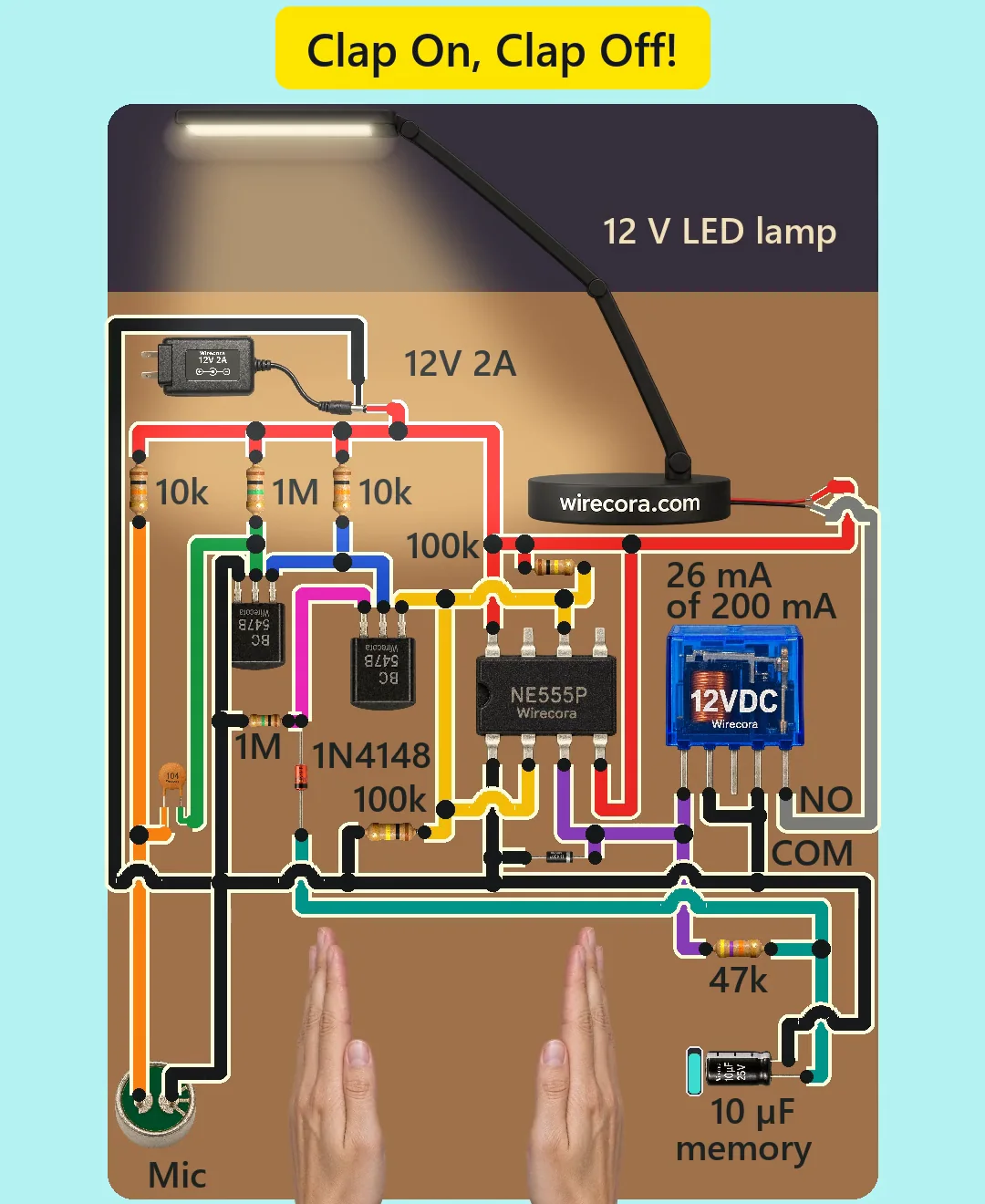
Parts
- NE555P timer, DIP-8
- Two BC547B NPN transistors, TO-92: Q1 the amplifier, Q2 the switch
- Electret microphone, two pads: OUT and GND (10 V maximum)
- Resistors, 1/4 W: R1 10 k (mic bias), R2 1 M (Q1 base), R3 10 k (Q1 collector), R5 100 k and R6 100 k (hold pins 2 and 6 at half supply), R7 47 k (memory), R8 1 M (Q2 emitter)
- C1 100 nF ceramic capacitor (printed 104), from the mic to Q1
- CM 10 uF 25 V electrolytic capacitor, the memory (stripe is the minus side)
- D1 1N4007 diode across the relay coil
- D2 1N4148 diode in Q2's emitter
- 12 V relay with a 400 ohm coil (SRD-12VDC-SL-C type; contacts 10 A at 30 V DC)
- 12 V LED desk lamp, about 6 W (0.5 A)
- Regulated 12 V 2 A adapter and a DC jack to plug it into (centre pin plus)
- Recommended, not drawn in the Short: a 10 nF capacitor from 555 pin 5 to minus, and 100 nF plus 100 uF across the 555's supply pins
How it is wired
- 12 V plus (jack centre) to 555 pin 8 (VCC) and pin 4 (RESET), to the top ends of R1, R2, R3 and R5, and to the lamp's plus (red) lead.
- 12 V minus (jack sleeve) to 555 pin 1 (GND), the mic's GND pad, Q1's emitter, the bottom end of R6, one end of R8, CM's minus leg, one relay coil pin, D1's anode (plain end) and the relay's COM contact.
- Mic OUT pad to the other end of R1 and to one leg of C1.
- The other leg of C1 to Q1's base and to the other end of R2.
- Q1's collector to the other end of R3 and straight to Q2's base (no extra resistor: R3 already limits the current to about 1.2 mA).
- Q2's emitter to D2's anode and to the other end of R8. D2's cathode (band) to CM's plus leg and to one end of R7.
- Q2's collector to 555 pins 2 (TRIG) and 6 (THRES), which are joined, and to the meeting point of R5 and R6.
- 555 pin 3 (OUT) to the other end of R7, to the other relay coil pin and to D1's band (cathode).
- Relay NO contact to the lamp's minus (black) lead. Relay NC, 555 pin 5 and pin 7 stay unconnected (or put the recommended 10 nF on pin 5).
- Relay pins differ between makers: find the coil pins, COM and NO on your relay's datasheet or with a multimeter.
How it works
- R5 and R6 hold 555 pins 2 and 6 at about 6 V, between the 555's 4 V trigger level and its 8 V threshold. There, the 555 keeps whatever output it has: it works as a flip-flop with two steady states.
- CM is the memory. Through R7 it slowly follows the 555 output (time constant 47 k x 10 uF = 0.47 s): near 0 V while the lamp is off, about 10 V while it is on.
- The mic sits at about 9 V through its 10 k bias, under its 10 V limit (assuming it draws 0.3 mA). R2 keeps Q1 switched fully on, so its collector sits near 0 V and Q2 is off.
- A clap swings Q1's base down through C1 for a few milliseconds. Q1 turns off, its collector jumps up through R3, and Q2 turns on and ties pins 2 and 6 to the memory.
- Lamp off: the memory is low, so pins 2 and 6 are pulled below 4 V and the 555 output goes high. Lamp on: the memory is high, the path through D2 cannot pull down, and the clap pulse lifts pins 2 and 6 above 8 V through Q2's base and collector, so the output goes low.
- When the clap ends Q2 turns off, pins 2 and 6 return to 6 V and the new state holds. CM then moves towards the new output, so a second sound within about half a second finds it in between and changes nothing.
- The 555 output (about 10 to 10.5 V) drives the relay coil directly: about 25 mA of the 200 mA the 555 can supply, above the coil's 9 V pull-in. The relay's NO contact joins the lamp's minus lead to minus and the lamp lights. D1 catches the coil's voltage kick when it switches off.
- D2 and R8 protect Q2: without them its emitter would sit on the memory's 10 V while its base is near 0 V, beyond the BC547's 6 V reverse limit.
- The whole circuit takes about 12 mA idle and about 0.5 A with the lamp on, of the adapter's 2 A.
What the video simplifies
- The hands clap much slower than real ones, and the sound arcs are slowed down: real sound reaches the mic in about a millisecond.
- The room's light change is shown stronger than a 6 W desk lamp gives. The lamp is assumed to be 12 V 6 W.
- The parts are drawn far larger than real next to the hands, and the adapter smaller than real. The adapter's lead is shown going straight to the circuit; build it with a DC jack.
- The 555's pin 5 is left open and no supply capacitors are drawn, for lack of room. A real build should add 10 nF from pin 5 to minus and 100 nF plus 100 uF across the 555's supply.
- Any loud bang (a door, a dropped book, a shout close to the mic) switches it too, and turning off needs a louder clap than turning on: clap within about half a metre of the mic.
- After plugging in, the lamp may start on or off; one clap sets it.
- The viral original used a single-shot latch; this version uses a 555 flip-flop with an RC memory, adds the diode and resistor that protect the switch transistor, and runs everything from one 12 V adapter.
- The claps and the relay clicks are made for the video. The circuit was checked by simulation and datasheets, not built.
Everything here runs on 12 V DC from a regulated adapter. Never build a clap switch on mains without a proper enclosure and a relay rated for it.
Build it yourself
The wiring board has no 555, microphone or capacitors yet, so this one cannot be opened on it. Start with the guided first build on the wiring board, where a circuit really works as you wire it, then try the ready-made ones.
Your first circuit, step by stepAll circuits from the Shorts
Stuck, or built it?
Ask about this circuit or show your build in the Wirecora Discord. Questions get an answer every day.