Coin-eating robot bank with an Arduino Nano, an FC-51 IR sensor, an SG90 servo and an OLED counter
Set a coin on the robot's scoop. Its eyes light up and the little screen wakes, the arm swings the coin up to its mouth, the jaw flap snaps, the coin drops into its clear belly and the count goes up by one. The arm swings back slowly, the eyes go out and the screen sleeps until the next coin. The count is saved, so it is still there after you switch it off.
From the Short This Robot Eats Your Coins and Counts Every One (posted 27 October 2026). Opens on YouTube.
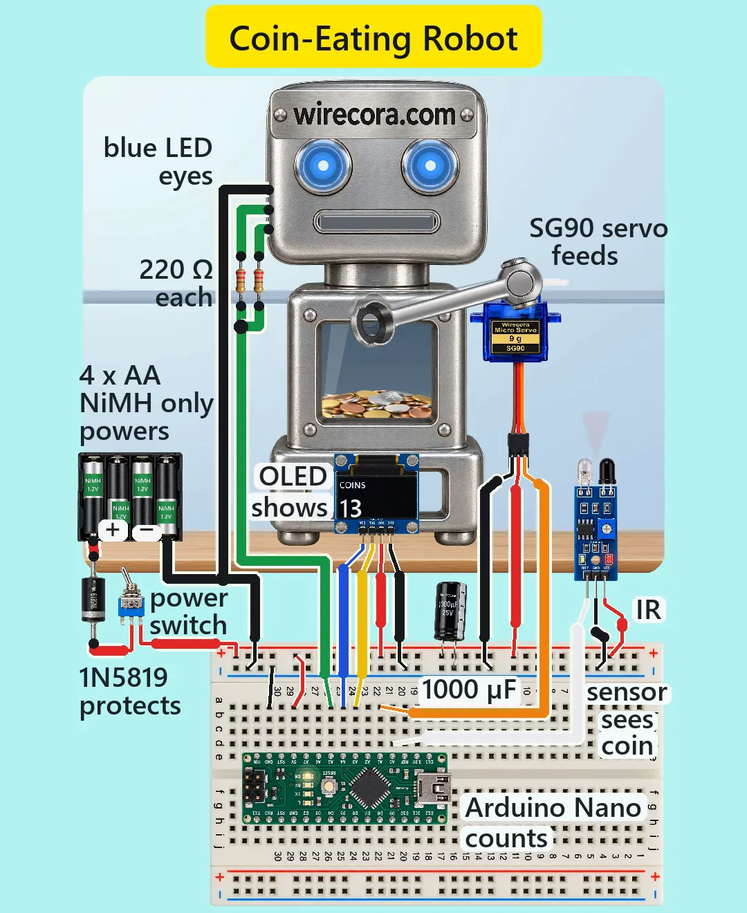
Parts
- Arduino Nano, 5 V, 16 MHz (an Uno works the same with the same pin numbers)
- FC-51 IR obstacle sensor, pins OUT, GND, VCC (OUT goes LOW while something reflects its light back; a trimmer sets the range)
- SG90 micro servo (rated 4.8 V, about 5 V; about 1.8 kg·cm; plug brown = GND, red = +, orange = signal)
- 0.96 inch I2C OLED, 128 x 64, SSD1306 (pins GND, VCC, SCL, SDA)
- Two blue 5 mm LEDs for the eyes, each with its own 220 ohm resistor
- 1000 uF 25 V electrolytic capacitor
- 1N5819 Schottky diode (40 V, 1 A)
- Small toggle switch (SPDT; only the middle lug and one end lug are used)
- 4 x AA holder with four rechargeable NiMH cells (1.2 V each). NiMH only: four fresh alkaline cells give too much voltage for this circuit
- Half breadboard with + and - rails, and jumper wires
- The robot: a box with a clear belly, a mouth slot with a light spring flap, a matte black scoop with a 15 mm hole in its floor on the end of the servo arm, a stand that holds the IR sensor looking up through that hole, and a bracket for the servo
How it is wired
- Battery + (red) to the 1N5819 anode (the plain end). The diode's band end (cathode) to the switch's middle lug, and the switch's end lug to the + rail. Diode and switch can be in either order; they are in series.
- Battery - (black) to the - rail. That rail is the ground for every part.
- Nano 5V pin to the + rail and Nano GND to the - rail. Use the 5V pin, not VIN: VIN goes through the Nano's regulator and needs about 7 V or more.
- 1000 uF across the rails next to the servo: long leg (+) on the + rail, striped leg (-) on the - rail.
- FC-51: VCC to the + rail, GND to the - rail, OUT to A0.
- SG90: red to the + rail, brown to the - rail, orange (signal) to A1.
- OLED: VCC to the + rail, GND to the - rail, SCL to A3, SDA to A4. The sketch drives it with software I2C on those two pins, so the wires drop straight down without crossing.
- Eyes: A5 to two 220 ohm resistors, one per LED, each into one LED's long leg (anode). Both short legs (cathodes) to the - rail.
- Leave VIN, RST, REF, 3V3, A2, A6, A7, D13 and the whole D0 to D12 row free.
- Mount the sensor under the scoop's hole, looking straight up, and turn its trimmer just past the point where the empty scoop trips it, so only a coin does.
How it works
- The FC-51 shines infrared light up through the 15 mm hole. With the scoop empty, nothing reflects within its set range and OUT stays HIGH. A coin bounces the light back, OUT goes LOW and the sketch sees it on A0.
- The sketch lights the eyes (A5 HIGH), wakes the screen to show the count, then waits 0.2 s and checks again. If the IR is clear by then it was only a finger passing, and nothing moves.
- If the coin is still there, the servo turns from 20 to 158 degrees, one degree every 3 ms: 138 degrees in about 0.41 s, well inside the SG90's speed. The scoop tips the coin into the mouth slot, it pushes the spring flap in and falls into the belly.
- 0.3 s later the count goes up by one, is saved in EEPROM and shown. Then the arm goes back at half speed (about 0.83 s), the eyes go out and the screen switches off 0.6 s later to save power.
- The count lives in EEPROM, so it survives switching off. EEPROM.put writes only the bytes that changed, and each cell takes about 100,000 writes: about 100,000 coins.
- Power: four fresh NiMH cells give about 5.6 V and the 1N5819 drops 0.25 to 0.35 V, so the rail is about 5.35 V, under the ATmega328P's 5.5 V rating and its 6.0 V absolute maximum (for a short time right after charging it can reach about 5.5 V, right at that rating). As the cells run down the rail falls to about 4.5 V nominal and 3.9 V when it is time to recharge.
- Why the diode: if the pack goes in backwards, it blocks the current and nothing is damaged. A Schottky is used because it loses only about 0.3 V.
- Why only NiMH: four fresh alkaline cells are about 6.4 V, and even after the diode the chip would see about 6.1 V, above its 6.0 V maximum.
- Currents: idle about 69 mA (about 27 hours on 1900 mAh cells). A feed takes about 0.34 A and a jammed arm about 0.74 A, under the diode's 1 A. The 1000 uF keeps the rail steady when the servo starts, so the Nano does not reset.
- The eyes: about (5.35 - 3.3) / 220 = 9.3 mA per LED, 18.6 mA for both from A5, under the pin's 20 mA recommended limit (40 mA absolute).
- Load: the light arm and coin ask about 0.1 kg·cm of the servo, against its 1.8 kg·cm.
- The OLED and the IR module run from the same 5.35 V rail. Both are sold for 3.3 to 5 V, so this is a little over their stated top: the FC-51's LM393 comparator is rated far higher, and most of these OLED boards carry their own 3.3 V regulator that takes up to 6 V.
The code: coin_bot.ino
The Arduino code for this circuit is in the Wirecora Discord, in the channel #arduino-code (owner’s choice, 14 October 2026: the code lives where you can ask about it). It is a plain .ino file you can download there.
The sketch the Short was animated from, replayed against the scene in the video; it has not been run on a real board yet. It needs the Servo and EEPROM libraries that come with the Arduino IDE and U8g2 (by olikraus) from the Library Manager. If the arm stops short of the mouth or hits the base, change REST and FEED to suit your horn.
What the video simplifies
- The electronics are drawn larger than real next to the robot, and the servo is drawn side-on so you can see the arm turn.
- The servo bracket and the sensor stand are not drawn; in a build both hold their parts in place.
- The IR beam is drawn red so you can see it; real infrared is invisible.
- The eye wiring is drawn on the outside; in a build it runs behind the robot's face.
- The trimmer setting, the scoop rim holding the coin until near the top, the spring jaw, the arm's weight, the servo currents and 1.40 V fresh cells are assumed. The screen write is assumed to take about 0.1 s, and which of the FC-51's two LEDs is its power LED is assumed.
- The coin is drawn smaller once it is in the belly, and the soft light glint that sweeps the robot after each coin is decoration, not part of the circuit.
- The count starts at 12 again each time the clip loops; the real count only goes up.
- It counts coins, not money: every coin is one. A very dull, dark coin may not reflect enough IR to be seen, and the FC-51 needs shade from direct sunlight.
- The coin designs are made up, and all the sounds are synthesised.
- This circuit was checked by simulation and against the datasheets, not built.
Everything runs on four AA NiMH cells (about 5 V DC); no mains wiring. Use NiMH cells only: four fresh alkaline cells can damage the Nano. Never short the battery leads, cells can get hot. The servo arm can pinch small fingers: keep the arm light and switch off before you reach into the mechanism. Coins are a choking hazard: keep the bank and loose coins away from small children.
Build it yourself
The wiring board cannot run an Arduino program yet, so this one cannot be opened on it. Start with the guided first build on the wiring board, where a circuit really works as you wire it, then try the ready-made ones.
Your first circuit, step by stepAll circuits from the Shorts
Stuck, or built it?
Ask about this circuit or show your build in the Wirecora Discord. Questions get an answer every day.