Continuity and diode tester with a BC547 and a buzzer
Touch the two probes to a wire, a good fuse, or a diode with its band towards the black probe: the buzzer beeps and the green LED lights. A blown fuse stays silent, and so does a diode the wrong way round. That is how you find which end of a diode is which: it beeps one way only.
From the Short Beeps One Way Only: Diode + Fuse Tester | BC547 (234K views, posted 11 October 2026). Opens on YouTube.
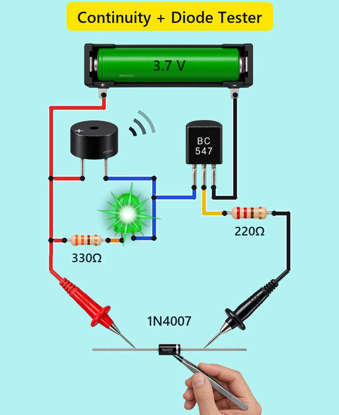
Parts
- BC547 NPN transistor, TO-92 (onsemi datasheet: flat face towards you, legs down: C, B, E from the left)
- Active buzzer rated for 3 to 5 V (it beeps by itself at about 2.3 kHz and takes about 30 mA; a + mark shows its plus leg). The one drawn is a 3 V type that works from 1.5 to 4 V. A 5 V-only type may stay quiet on this cell.
- Green 5 mm LED (the long leg is the anode)
- 330 ohm resistor for the LED (bands orange, orange, brown, gold)
- 220 ohm resistor for the transistor's base (bands red, red, brown, gold)
- 3.7 V Li-ion cell (18650) in a holder: 4.2 V full, 3.0 V empty
- Red and black test probes (multimeter type)
- To try it: a glass fuse (the video uses a 1 A 5x20 mm one) and a 1N4007 diode (the band is the cathode)
How it is wired
- Cell plus (+ tab) to the buzzer's + leg, one end of the 330 ohm and the red probe.
- The other end of the 330 ohm to the LED's anode (long leg).
- The buzzer's minus leg and the LED's cathode (short leg) to the BC547 collector (C).
- BC547 emitter (E) to cell minus.
- BC547 base (B) to the 220 ohm; the other end of the 220 ohm to the black probe. The black probe does not go to cell minus.
- That is all: the part you test closes the path from the red probe to the black probe.
How it works
- With nothing between the probes, no current reaches the base, so the transistor is off and the tester takes practically no current. That is why it needs no on/off switch.
- Join the probes through a wire or a good fuse: current flows from plus through the part and the 220 ohm into the base, (3.7 - 0.75) / 220 = about 13 mA.
- That is far more than the BC547 needs: it carries about 41 mA here on 13 mA of base current, a gain of only 3, while a BC547 has a gain of about 100 or more at these currents. So it switches fully on, with only about 0.09 V from collector to emitter. The collector pulls the buzzer's minus leg and the LED's cathode down: the buzzer takes about 36 mA and the LED (3.7 - 0.09 - 2.03) / 330 = about 4.8 mA. Together that is 41 mA of the BC547's 100 mA, and 13 mW of its 625 mW.
- A diode with its band towards the black probe has its anode on plus, so it conducts. It drops about 0.7 V, the base still gets about 10 mA, and the beep is the same. Turn it round and it blocks. Even the most leakage the datasheet allows at room temperature (5 uA, and that at 1000 V), with a high-gain transistor and a full cell, leaves only 0.39 V on the buzzer: silent.
- Because the transistor is switched fully on, its gain does not matter, and it works across the cell's range. At 3.0 V the LED gets 2.8 mA and the buzzer 2.9 V; at 4.2 V, 6.2 mA and 4.1 V.
- It is not a resistance meter. Anything under about 6 k beeps loudly with any BC547. Above that it depends on the transistor's gain: a typical BC547B still beeps at 22 k and only chirps around 47 k, while a high-gain BC547C still beeps at 47 k and can sound weakly at 100 k. From about 220 k up it stays silent.
- The probes carry at most about 15 mA (13 mA at 3.7 V), and joining them cannot short the cell, because the 220 ohm is always in the path. The cell gives about 54 mA (62 mA when full) only while something conducts.
- Fixed from the popular version: the viral circuit wires the LED straight from plus to the collector, with no resistor. In simulation that is 188 mA in the LED (its limit is 25 mA) and 221 mA in the transistor (its limit is 100 mA), both far over their limits. Copy this one, with the 330 ohm.
- What it is not: an all-in-one component tester. It gives no value, fuse rating, capacitance or gain. A shorted diode beeps both ways. A capacitor only chirps while it charges (about 1.3 s for 1000 uF). A red or green LED with its anode on the red probe beeps and glows faintly; blue and white LEDs are unreliable (silent at 3.0 V). A transistor's junctions act like diodes. A leaky Schottky diode can beep the wrong way.
- There is no resistor from base to emitter, so a wet finger across the tips (about 47 k) can make it chirp, or even beep with a high-gain BC547C. Use clean, dry probes; a BC547A or B gives fewer false beeps than a C.
What the video simplifies
- A hand with tweezers holds each part on the probe tips and turns the diode in mid-air. In real use you touch the probes to the part's leads.
- The LED starburst and the sound arcs are graphics. At 4.8 mA a 5 mm LED is dimmer than drawn, and it ramps up over 0.1 s in the video where the real switch takes microseconds.
- The beep is synthesised at 2.7 kHz; a real active buzzer is about 2.3 kHz.
- The cell is labelled 3.7 V, its nominal voltage. In use it is anywhere from 3.0 to 4.2 V.
- The buzzer drawn is a 3 V type. On a full 4.2 V cell it gets 4.1 V, 0.1 V over the top of its 1.5 to 4 V range, so use one rated for 3 to 5 V.
- The fuse's rating is not tested: a good 1 A fuse and a good 10 A fuse beep the same.
- The cell-minus wire and the black probe's wire are both drawn black, but they are not joined: the black probe goes to the 220 ohm.
- The printing on the diode is generated, and while the diode sits the wrong way round (before the turn) it reads mirrored.
- This circuit was checked by simulation (ngspice, at 3.0, 3.7 and 4.2 V and at low and high transistor gain) and against the datasheets, not built.
Everything runs on one 3.7 V cell, and the probes carry at most about 15 mA, so the tester itself is safe. Test only unpowered, discharged parts: a live circuit or a charged capacitor across the probes can damage the transistor and gives wrong answers. Charge the Li-ion cell only in a proper charger, use a protected cell, and keep its bare terminals from touching each other.
Build it yourself
The wiring board has the BC547, an LED, resistors, the 1N4007 and a buzzer, but no 3.7 V cell, test probes or fuse, and its buzzer is a 5 V type that needs at least 4 V. So it can be built there only with the 5 V supply standing in, and the numbers on this page are for 3.7 V. Start with the guided first build on the wiring board, where a circuit really works as you wire it, then try the ready-made ones.
Your first circuit, step by stepAll circuits from the Shorts
Stuck, or built it?
Ask about this circuit or show your build in the Wirecora Discord. Questions get an answer every day.