Puppy costume tail that wags when a candy drops, with an IR sensor, a 555 and a gear motor
A candy drops into the pumpkin pail. An IR sensor on the pail sees it fall past, a 555 timer starts, and a small gear motor in the backpack rocks the plush tail 18 degrees each way, about two wags a second, for 3 seconds. Then the tail hangs still until the next treat. No code and no microcontroller.
From the Short Drop Candy in the Bucket and This Puppy Costume Wags Its Tail (posted 29 October 2026). Opens on YouTube.
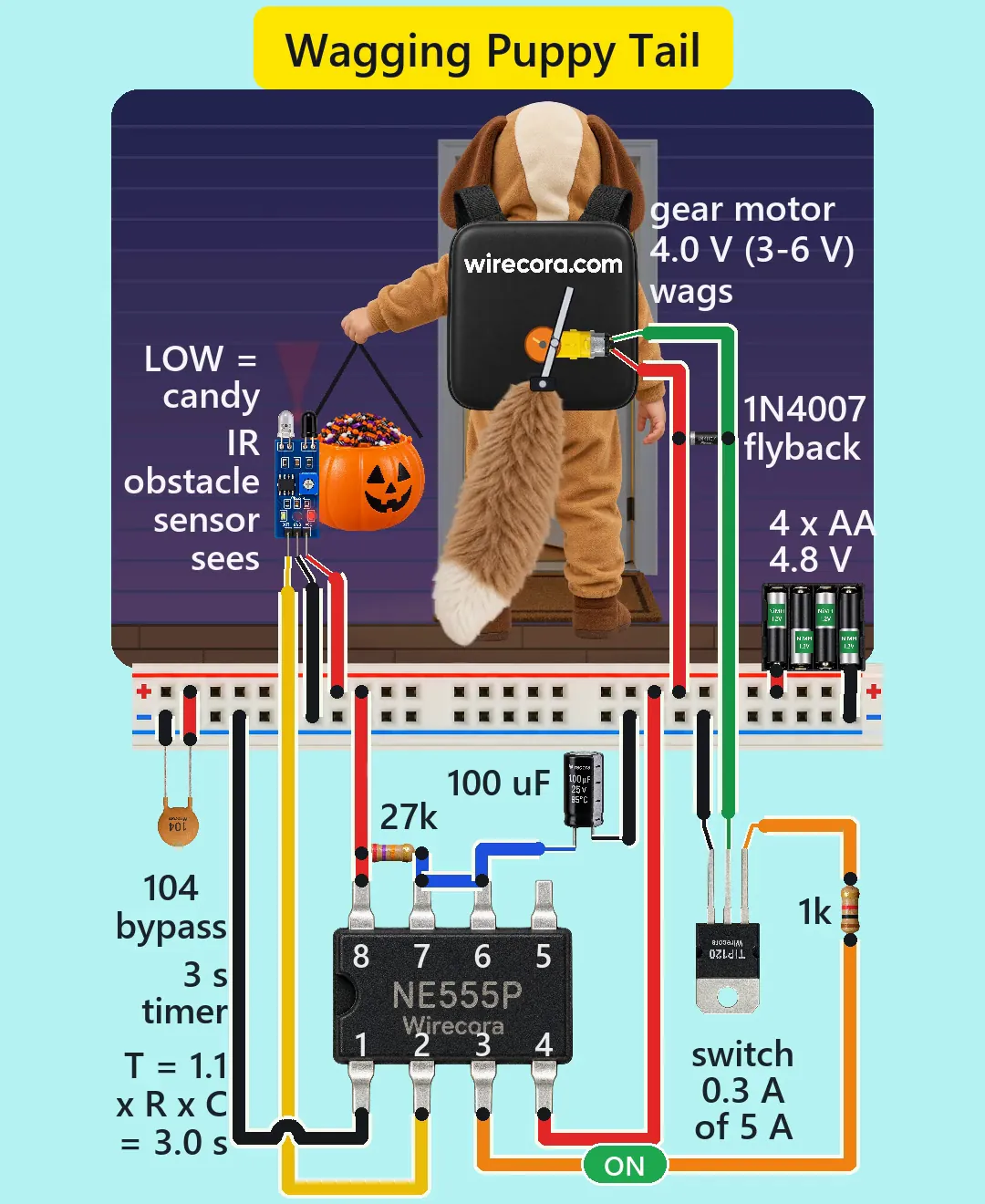
Parts
- FC-51 IR obstacle sensor module (3.3 to 5 V; pins OUT, GND, VCC left to right; its output goes LOW when it sees something; range 2 to 30 cm (0.8 to 12 in), set with its trimmer; detection angle about 35 degrees). It has its own pull-up resistor on the board (about 10k, an assumed value).
- NE555 timer, DIP-8 (notch to the left: pin 1 bottom left, pins 1 to 4 along the bottom, 5 to 8 along the top from the right; 4.5 to 16 V)
- TIP120 Darlington transistor, TO-220 (B, C, E from the left with the print facing you; the metal tab is the collector)
- TT gear motor, 1:48 (3 to 6 V; 90 rpm at 3 V, 200 rpm at 6 V, no load; not polarised)
- 1N4007 diode across the motor (the flyback diode)
- 27k resistor and 1k resistor, 1/4 W
- 100 uF 25 V electrolytic capacitor (sets the time; the stripe side is minus)
- 100 nF ceramic capacitor, marked 104 (across the supply beside the chip)
- 4 x AA holder with four NiMH cells (4.8 V). Use NiMH, not alkaline and not a power bank; see Works and Safety.
- A crank and a slotted lever to turn the motor's turning into a rocking motion, a plush tail about 43 cm (17 in) long, a small backpack box to hold the motor, and a pumpkin pail
- A breadboard (its power rails are enough)
How it is wired
- Battery plus (red) to the + rail and battery minus (black) to the - rail. Put the 100 nF (104) across the two rails next to the 555.
- 555 pin 8 (VCC) and pin 4 (RESET) to +. Pin 1 (GND) to -. Pin 5 (CONT) is left unconnected.
- Sensor VCC to +, sensor GND to -. Sensor OUT to 555 pin 2 (TRIG). Nothing else goes on that wire.
- 27k resistor from pin 8 (+) to pin 7 (DISCH). Join pins 7 and 6 (THRES) with a short wire.
- 100 uF capacitor from pin 6 to the - rail: long lead (plus) to pin 6, stripe (minus) to -.
- 555 pin 3 (OUT) through the 1k resistor to the TIP120 base (B). TIP120 emitter (E) to the - rail.
- TIP120 collector (C) to one motor wire. The other motor wire to the + rail. The motor is not polarised, so either wire works; swapping them only turns the crank the other way.
- 1N4007 across the motor: band (cathode) on the motor wire that goes to +, plain end on the wire that goes to the TIP120 collector.
- Mount the motor in the backpack with a crank disc on its shaft. A pin on the disc sits in a slot in a lever. The lever pivots at the top of the tail, so each turn of the disc rocks the tail once to one side and back.
- Clip the sensor to the pail so its two LEDs face straight up over one side of the opening, and set its trimmer with a real candy to about 12 cm (5 in). Keep the handle and the child's hand out of its cone.
How it works
- With nothing in front of the sensor, its output is HIGH, about 4.9 V: the module's own pull-up holds it there. The 555 trigger (pin 2) sits far above one third of the supply (1.6 V), so nothing happens. The 555 output stays LOW, the TIP120 is off and the motor is still.
- A candy falls through the sensor's beam. The output drops LOW, to about 0.2 V, for a few milliseconds. The 555 starts a timing run when pin 2 goes below one third of the supply, so that short LOW is plenty. The sensor and the 555 are joined by one wire.
- The 555 output (pin 3) goes HIGH and stays HIGH while the 100 uF capacitor charges through the 27k resistor up to two thirds of the supply. That time is 1.1 x R x C = 1.1 x 27k x 100 uF = 2.97 s, about 3 seconds. To a first order it does not depend on the battery voltage, because both thresholds are fractions of the supply. A leaky electrolytic can add a few percent. A capacitor with 20 percent tolerance gives 2.4 to 3.6 s. A 47k resistor instead of the 27k gives about 5 s.
- A 555 monostable cannot be retriggered. While the output is HIGH, later LOWs on pin 2 are ignored, so a second candy does not restart the count. At the end of the 3 seconds, if pin 2 is back HIGH, the 555 discharges the capacitor through pin 7 and the output goes LOW. If the sensor still sees something (pin 2 still LOW), the output stays HIGH until pin 2 rises above one third of the supply, and only then does it go LOW.
- The output pushes about 2 mA through the 1k resistor into the TIP120 base: (3.3 V - 1.3 V) / 1k, using the NE555's typical high level and an assumed base voltage. Even at its lowest guaranteed high level (2.75 V) it is still about 1.3 mA. The TIP120 has a gain of at least 1000 (at 0.5 A), so that base current could carry over an amp and the transistor is fully on. It switches the motor's minus side: the motor sits between + and the collector, and the emitter is on -.
- The motor gets about 4.0 V (the battery's 4.9 V under load minus about 0.9 V across the TIP120), inside its 3 to 6 V range. It draws about 0.3 A on average, with peaks near 1 A each time the tail turns around (both are estimates from the simulation, not measurements). That is 0.3 A of the TIP120's 5 A, and it loses about 0.27 W, which it handles without a heatsink. The 555 gives only 2 mA of its 200 mA.
- The crank turns about 2 times a second (an estimate from the motor's two datasheet points and the tail's load) and makes one wag per turn. Six turns fit into the 3 seconds. The lever ratio is about 0.31, which gives a swing of 18 degrees each way.
- When the 555 lets go, the motor's coil kicks back for under a millisecond. The 1N4007 takes that current, so the TIP120 sees only a little more than the supply, about 6 V at most, far under its 60 V rating. A TT gearbox is hard to turn backwards, so the motor stops within a fraction of a second.
- Standing by, the sensor takes about 40 mA (an estimate: most of it its infrared LED, and boards differ) and the 555 about 3 mA: about 45 mA in all. Four 1900 mAh NiMH cells last about 40 hours of standby. Wagging takes about 0.35 A, so a tail that never stops (a full pail) empties the cells in about 5 hours.
- Why NiMH: four fresh alkaline cells give about 6.4 V, over the FC-51's 5 V rating. Four NiMH cells give about 4.8 V under load. Many USB power banks switch themselves off when the load is very small. The cut-off level differs by model, often somewhere under 50 to 100 mA (not from a datasheet), and this circuit idles at about 45 mA, so a power bank may switch off between candies. Straight off the charger the pack can read up to about 5.6 V for a while, a little over the sensor's 5 V rating. Recharge the cells when the wag slows: at 1.1 V a cell the pack is 4.4 V, under the 555's 4.5 V minimum, and the chip is no longer guaranteed to work (it may keep working a little lower).
- It wags for anything that passes through the beam, a hand too. A pail full to the rim keeps the beam blocked, so the tail never stops. That is the joke in the Short.
- The 555 can fire one 3 second pulse when you first connect the battery, because its state at power-up is not defined (not every time, and not tested here). The tail wags once. It is harmless.
- Limits of the sensor: the FC-51 is an unmodulated reflective sensor. Bright sunlight or a lamp shining into its receiver can blind it or trigger it, and a dark candy wrapper reflects less than the white card you usually set the trimmer with, so set the range with a real candy. On a long wire beside the motor, pin 2 can pick up noise. If that happens, try a 10 nF capacitor from pin 2 to - (not drawn and not tested), and 10 nF from pin 5 to -, as the 555 datasheet's own timer circuit shows.
What the video simplifies
- The red cone is drawn to show where the sensor looks. Infrared is invisible. The cone's short afterglow and its 12 cm (5 in) range are drawn for the Short.
- The tail's weight (25 g), the motor's speed and current under that load, the TIP120's 0.9 V drop and 1.3 V base voltage, and the motor's stall current (about 1.5 A, an estimate: the datasheet we had does not give it) are typical or assumed values, not measured ones.
- The motor is drawn stopping exactly where it started, so the clip loops. A real tail stops anywhere in its swing, within 18 degrees of straight down.
- The sensor is drawn about 2.6 times larger than real, the motor about 2 times and the backpack about 1.5 times. The NE555 is drawn large so its print reads, about 3.5 times the size of the TIP120, although the two parts are about the same size in real life.
- The breadboard circuit and the battery holder, which would ride in the backpack, are drawn opened out below and beside the child, several times larger than true scale.
- The tail is drawn fuller than a plain plush tail. The toddler's bounce is staged. The hood ears and the pail do not swing; the pile of candy dips a few pixels instead.
- The 3 second run follows from the 27k and 100 uF values and the two wags a second is an estimate. Time is not sped up.
- The sounds are synthesised.
- This circuit was checked by simulation (ngspice) and against the datasheets, not built.
Everything runs on 4.8 V from four NiMH cells. Charge NiMH cells only in a charger made for them. Keep the cells and the electronics in a closed backpack box that a small child cannot open, and take the batteries out when you store the costume. Do not use alkaline cells (6.4 V is too high for the sensor). Make sure no wire can be pinched by the crank, and keep the tail's swing clear of the wires. The TIP120 stays cool at 0.3 A. Bright sunlight or a lamp can set the sensor off.
Build it yourself
The wiring board has an IR obstacle sensor, a TIP120, a 1N4007 and a DC motor, but no 555 timer, no capacitors and no 4 x AA holder yet, so this one cannot be opened on it. Start with the guided first build on the wiring board, where a circuit really works as you wire it, then try the ready-made ones.
Your first circuit, step by stepAll circuits from the Shorts
Stuck, or built it?
Ask about this circuit or show your build in the Wirecora Discord. Questions get an answer every day.