Crawling porch zombie with a PIR sensor, two BC547s, an IRFZ44N and a worm gear motor
A trick-or-treater walks onto the porch and the legless zombie by the railing lunges at their feet, claw first, slides back and lunges again, then parks in exactly the same spot for the next visitor. A motion sensor, two transistors and a MOSFET run it: there is no code and no microcontroller.
From the Short Walk Up to This Porch and a Zombie Lunges at Your Feet (posted 25 October 2026). Opens on YouTube.
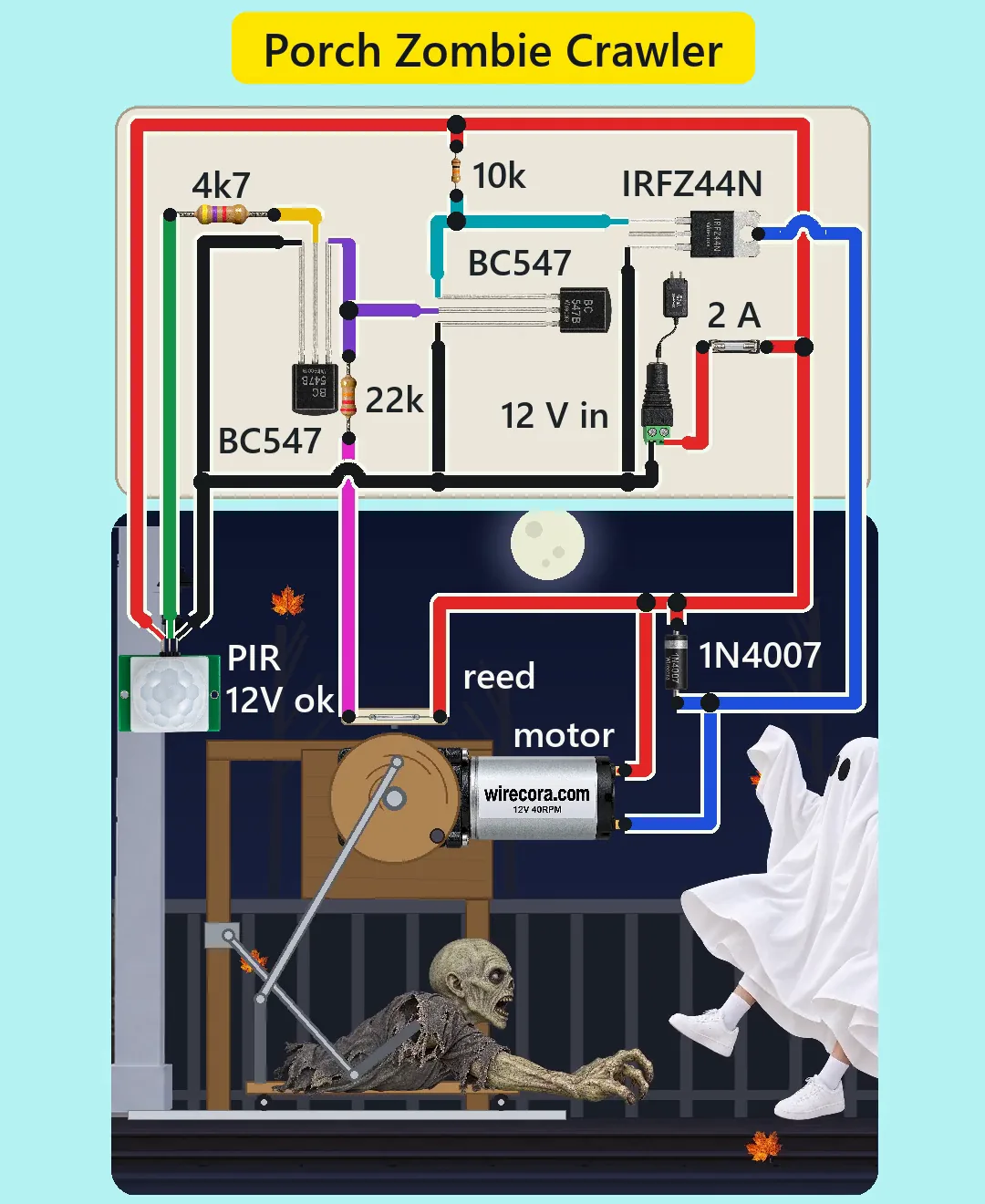
Parts
- HC-SR501 PIR motion sensor module (4.5 to 20 V supply, under 2 mA; OUT gives 3.3 V while it sees motion; jumper on L, single trigger; time trimmer near its minimum)
- Two BC547 NPN transistors, TO-92 (flat face towards you, legs down: C, B, E from the left)
- IRFZ44N N-channel MOSFET, TO-220 (G, D, S from the left with the print facing you; the metal tab is the drain; rated 55 V, 49 A, gate 20 V max)
- 1N4007 diode across the motor (flyback)
- Resistors, 1/4 W: 4.7k (PIR to the first transistor), 10k (gate pull-up), 22k (reed to the second transistor). Recommended extra: 100k (second transistor's base to GND)
- Reed switch, normally open, two leads (0.5 A max; it carries only 0.5 mA here) and a small disc magnet, about 10 mm, glued on the crank disc's rim
- 2 A quick-acting 5 x 20 mm fuse in a holder
- DC barrel jack (5.5 x 2.1 mm, centre pin +) and a regulated 12 V 2 A adapter, centre positive
- JGY-370 type 12 V 40 rpm worm gear motor, 1:150 (seller's table: no load 60 mA, rated 2 kg·cm at 0.6 A, stall 7.5 kg·cm at 1.7 A; the worm gear holds its position when unpowered). Recommended extra: a 100 nF ceramic capacitor across its terminals
- The prop: a light foam zombie torso (about 0.8 kg with its sled) on a small wheeled sled, a short aluminium rail, a plywood crank disc on the motor shaft (crank pin about 11 cm from the centre), a steel push rod from the crank pin to a post on the sled (about 33 cm of travel), a second rod from a fixed point on the stand to the zombie's arm, and a plywood stand
How it is wired
- Jack + (centre pin) through the 2 A fuse to the +12 V line. Jack minus is GND. One ground for everything.
- PIR VCC to +12 V and PIR GND to GND (the module has its own regulator and takes 4.5 to 20 V). The pin names are printed on the module beside its header.
- PIR OUT through the 4.7k to the base of the first BC547 (the PIR stage). Its emitter to GND.
- The PIR stage's collector to the base of the second BC547 (the park stage), and to one end of the 22k. The 22k's other end to one reed lead, the reed's other lead to +12 V. Recommended: a 100k from that base to GND, so it never floats.
- The park stage's emitter to GND. Its collector to the IRFZ44N gate, and the 10k from the gate to +12 V.
- IRFZ44N source to GND. Drain (the tab, or the middle leg, which is joined to it) to the motor's minus terminal. Motor plus terminal to +12 V.
- The 1N4007 across the motor: band (cathode) on the +12 V terminal, the other end on the drain side. Fit it at the motor with short leads, and the optional 100 nF beside it.
- Mount the reed switch on the stand beside the crank disc and glue the magnet on the disc's rim so it passes about 1 cm from the reed at the home position only: the crank pin at its back point, the zombie fully drawn back.
- Linkage: crank disc on the motor shaft, push rod from the crank pin to a post on the sled, sled wheels on the rail; one turn of the disc is one lunge and return. If the lunge comes out slower than the return, swap the two motor wires, and turn the diode round with them so its band stays on the +12 V wire.
- Aim the PIR down at the porch boards and tape over the sides of its dome, so it watches the steps and not the street.
How it works
- At rest the zombie is home, so the magnet holds the reed closed. 12 V through the 22k and the reed puts 0.51 mA into the park stage's base. That transistor is fully on and pulls the MOSFET gate to nearly 0 V: the MOSFET is off and the motor stands still. The whole circuit then draws only a few milliamps.
- A visitor walks into the PIR's view and OUT goes to 3.3 V. Through the 4.7k that is 0.55 mA into the PIR stage's base, plenty to switch it fully on. It pulls the park stage's base to GND, so the park stage turns off, the 10k pulls the gate up to 12 V (well above the IRFZ44N's 4 V maximum threshold, below its 20 V limit) and the motor runs.
- Why the transistors: the PIR gives 3.3 V and a few milliamps, the motor needs 12 V and up to 1.7 A. The PIR only drives a base; the MOSFET carries the motor current.
- Within a moment the crank disc leaves home and the reed opens. Now nothing feeds the park stage's base, so the motor keeps running even after the PIR's output falls. The motor stops only when the magnet comes round to the reed while the PIR is LOW: the zombie always finishes its turn and parks at home, and the self-locking worm gear holds it there.
- Under load the motor turns at about 36 rpm, one lunge every 1.7 s, and the sled reaches about 0.7 m/s at its fastest. The PIR's time sets the number of lunges: about 1.8 to 3.4 s gives two, 3.4 to 5 s three, 5 to 6.7 s four. Modules differ, and many cannot be set much below 3 to 5 s. In the Short it is set to about 3.5 s, so the zombie lunges three times and parks about 5 s after it started. The PIR then waits about 2.5 s before it can fire again.
- When the MOSFET switches off, the 1N4007 catches the motor's voltage kick (the drain peaks about 12.8 V in the simulation instead of spiking towards the MOSFET's 55 V limit).
- Currents: the motor about 0.35 A on average and 0.7 A at the hardest point of the stroke with a 0.8 kg foam prop (about 0.85 A at 1 kg), 1.7 A if it is held still. That stays under the 2 A fuse and the 2 A adapter. The MOSFET loses about 2 mW running and 51 mW stalled, so it needs no heatsink. The reed carries 0.5 mA and the resistors at most 14 mW of their 250 mW.
What the video simplifies
- The electronics are drawn several times larger than the porch and the motor about ten times its real size, so the pins and labels can be read; the adapter is drawn smaller than it is.
- The wires are drawn as an overlay over the scene, and in places over the child.
- The zombie's shirt is cut short so the sled, rail, rods and crank show; a store prop hides them under cloth.
- The magnet is drawn further from the reed than in a real build (about 1 cm), and the reed looks nearly the same open and closed; the park is shown by the magnet and the motion.
- The video has no 100k from the park stage's base to GND and no 100 nF across the motor. The circuit works without them (the simulation agrees), but both are good practice, so this page adds them.
- The motor figures come from a seller's table for a JGY-370 40 rpm worm gear motor, and the speed is taken as a flat 36 rpm under load. The 3 degree coast after power is cut, the reed's closing range of about 8 degrees either side and the 0.8 kg foam prop are assumed. At 0.8 kg the hardest point of the stroke needs about 2.9 kg·cm, above the 2 kg·cm rating but far below the 7.5 kg·cm stall; a heavy latex zombie needs a bigger gear motor and supply.
- The PIR time of about 3.5 s is a trimmer setting, and the PIR's 30 to 60 s warm-up after power-up is skipped.
- The store prop this is remade from also screams. This one has no speaker, so only the motor, the sled and the claw are heard, and all the sounds are synthesised.
- This circuit was checked by calculation, an ngspice simulation and the datasheets, not built.
Everything runs on 12 V DC from a regulated, certified 12 V adapter; no mains wiring. The crank, rods and sled can pinch fingers: cover the mechanism and unplug before you reach into it. If someone holds the zombie away from home, the motor keeps pushing at its 1.7 A stall current, which the 2 A fuse will not stop: do not leave it running unattended, or for a long night fit a polyfuse that holds 0.75 A and trips at 1.5 A in place of the fuse. Keep the zombie on the boards beside the railing, well away from the steps: it moves about 33 cm and must never reach a visitor, and a scare on a staircase can make a child step back and fall. Cats will set the PIR off too. Keep the adapter and the board dry and in a box, and tape the cables down so nobody trips. For very young trick-or-treaters, unplug it.
Build it yourself
The wiring board has no PIR sensor, reed switch, gear motor or linkage yet, so this one cannot be opened on it. Start with the guided first build on the wiring board, where a circuit really works as you wire it, then try the ready-made ones.
Your first circuit, step by stepAll circuits from the Shorts
Stuck, or built it?
Ask about this circuit or show your build in the Wirecora Discord. Questions get an answer every day.