Delay OFF timer with a 555
Press the button once: the 12 V lamp lights straight away, stays on for about 5 seconds and then switches itself off. Letting go of the button early changes nothing, and pressing it again while the lamp is on does not restart the time.
From the Short Delay OFF Timer Using 555 (209K views, posted 14 October 2026). Opens on YouTube.
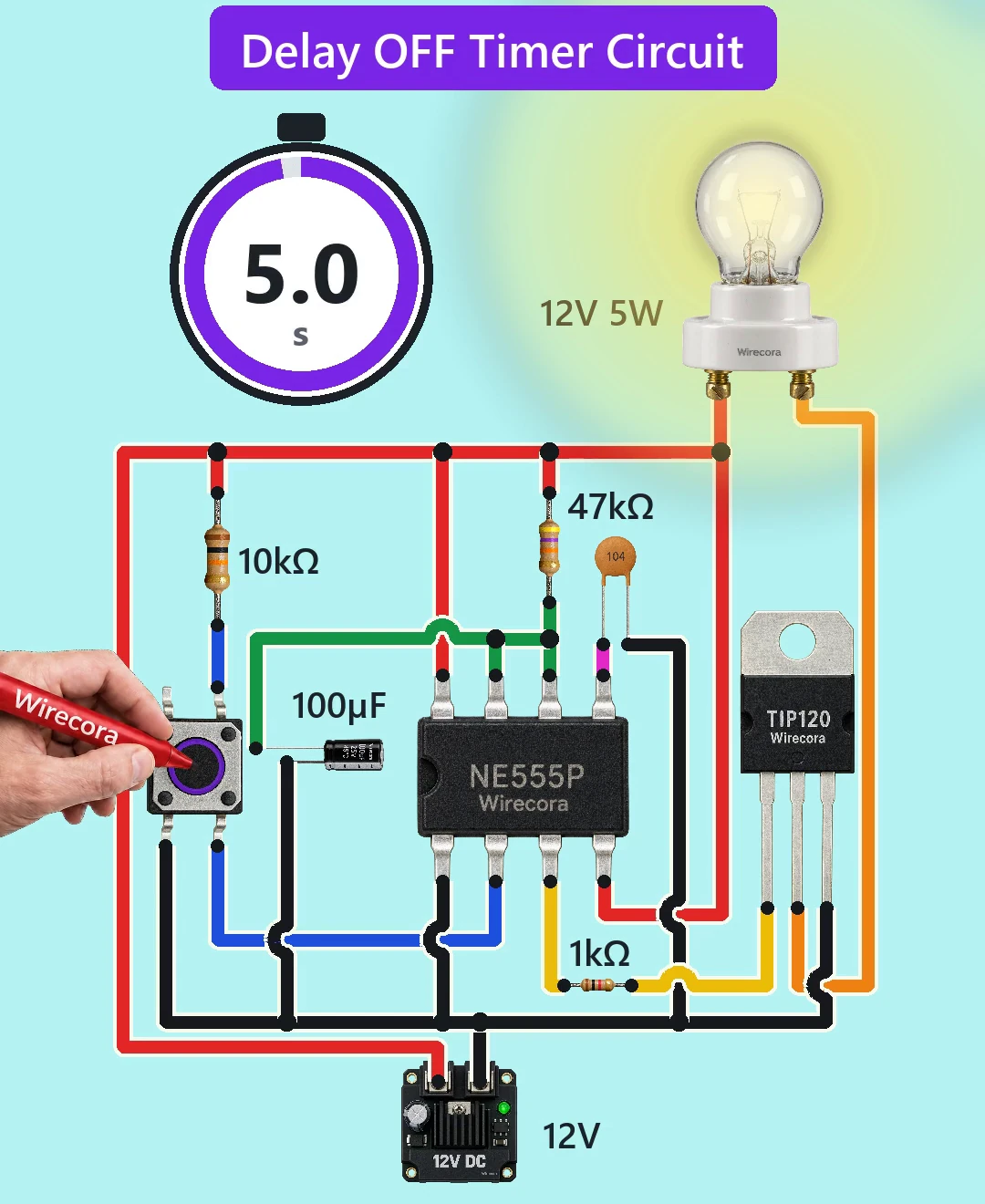
Parts
- NE555 timer, DIP-8 (notch on the left: pin 1 is bottom left; 1 GND, 2 TRIG, 3 OUT, 4 RESET, 5 CONT, 6 THRES, 7 DISCH, 8 VCC)
- TIP120 Darlington transistor, TO-220 (printed face towards you, legs down: B, C, E from the left; the metal tab is the collector)
- 6 mm push button (tactile switch) with four legs
- 47k resistor for the timing (bands yellow, violet, orange, gold)
- 10k resistor that holds pin 2 high (bands brown, black, orange, gold)
- 1k resistor for the transistor's base (bands brown, black, red, gold)
- 100 uF 25 V electrolytic capacitor for the timing (long leg plus, the stripe is the minus side)
- 100 nF ceramic capacitor (printed 104) on pin 5
- 12 V 5 W lamp in a holder with two terminals (a W5W car side-light bulb in its socket works)
- 12 V DC supply that gives at least 0.5 A (1 A leaves room for the lamp's cold start)
How it is wired
- Supply plus (+12 V) to 555 pin 8 (VCC) and pin 4 (RESET), to one end of the 47k, one end of the 10k and one terminal of the lamp.
- Supply minus to 555 pin 1 (GND), the 100 uF minus (stripe) leg, one leg of the 100 nF, one side of the push button and the TIP120 emitter (E). One common ground.
- The other end of the 10k to 555 pin 2 (TRIG) and to the other side of the push button, so pressing joins pin 2 to ground.
- On a four-leg button, two pairs of legs are joined inside and pressing joins the pairs. Use two legs diagonally opposite each other: that works whichever way round the button sits. Check with a meter if unsure.
- The other end of the 47k to 555 pin 6 (THRES) and pin 7 (DISCH), which are joined, and to the 100 uF plus (long) leg.
- 555 pin 5 (CONT) to the other leg of the 100 nF.
- 555 pin 3 (OUT) to the 1k; the other end of the 1k to the TIP120 base (B).
- TIP120 collector (C, the middle leg) to the lamp's other terminal. The lamp has no plus or minus side.
- Not drawn in the video, but the 555 datasheet strongly recommends it: a second 100 nF ceramic across pins 8 and 1, close to the chip.
How it works
- While nobody presses, the 10k holds pin 2 at 12 V. The 555's output (pin 3) is low and pin 7 holds the 100 uF empty, so the lamp is off.
- Pressing pulls pin 2 to ground, below a third of the supply (4 V). The 555 output jumps high (about 10.6 V) and pin 7 lets go of the capacitor.
- Pin 3 feeds the TIP120 base through the 1k: (10.6 - 1.4) / 1k = about 9 mA. A Darlington has a gain of about 1000, so the lamp's 0.42 A needs only about 0.4 mA. The transistor switches fully on and the lamp gets about 11.2 V.
- The 100 uF fills through the 47k. When it reaches two thirds of the supply (8 V), the 555 output goes low, pin 7 empties the capacitor and the lamp goes off. The time is T = 1.1 x 47k x 100 uF = about 5.2 s (5.17 s in a simulation).
- The 555 ignores new presses while it is timing. If you hold the button down for longer than 5.2 s, the lamp stays on until you let go.
- For a longer time, use a bigger resistor: 100k gives about 11 s. Every electrolytic capacitor leaks a little current, and the longer the time, the more the leak stretches it. With a very big resistor such as 470k the leak can be as big as the charging current, and the lamp might never switch off. For a minute or more, use a low-leakage capacitor and time your build.
- The TIP120 drops about 0.8 V, so it turns 0.33 W into heat and warms by about 20 C: no heatsink is needed. A cold lamp draws a short surge of about 3.8 A, under the TIP120's 8 A peak rating.
- The button carries only 1.2 mA. The 100 nF on pin 5 keeps the 8 V switching level steady: the datasheet draws 10 nF there and says a capacitor on pin 5 can improve operation, and 100 nF does the same job.
- The datasheet does not say which way the 555 starts up, so switching the supply on can start one timing period by itself. If the lamp lights for about 5 s at switch-on, that is why; it then switches off as usual.
What the video simplifies
- The countdown ring, the lamp glow and the press ring are drawn for the video. The clicks, the stopwatch ticks and the hum are synthesised.
- The lamp is drawn like a household bulb, but it is a 12 V 5 W lamp. The 12 V 5 W rating is our choice and is not printed on the drawn part.
- The countdown shows the calculated 5.2 s. Real parts vary: 5 % resistors and 20 % capacitors give about 3.9 to 6.5 s, and a leaky capacitor can stretch the time to about 6.3 s.
- The supply is drawn as a generic 12V DC terminal board, with plus on the left screw and minus on the right. Its marks are hidden under the red and black wires. Any 12 V DC adapter of 0.5 A or more does the job.
- In the video the 10k and the wire to pin 2 land on two legs of the button that are joined inside. That is correct, but the diagonal legs above are easier to get right.
- The button is pressed with the tip of a marker; a finger works the same.
- The viral original switches a 230 V mains bulb through a relay. This version uses a 12 V lamp and a transistor, so no mains is involved.
- This circuit was checked in a simulation (ngspice) and against the datasheets, not built.
Everything runs on 12 V DC, so nothing here can shock you. The lamp gets hot, so do not touch the glass while it is on. The TIP120's metal tab is joined to its collector: keep it away from other wires and from a metal case. Do not swap in a mains bulb. Switching 230 V or 120 V needs a rated relay or a ready-made timer module in a closed box, and in many countries an electrician.
Build it yourself
The wiring board has no 555 or capacitors yet, so this one cannot be opened on it. Start with the guided first build on the wiring board, where a circuit really works as you wire it, then try the ready-made ones.
Your first circuit, step by stepAll circuits from the Shorts
Stuck, or built it?
Ask about this circuit or show your build in the Wirecora Discord. Questions get an answer every day.