Flapping porch bat with a motion sensor, a TIP120 and a TT gear motor
Trick-or-treaters walk up to the door, a motion sensor sees them, and the big bat under the porch roof lights its red eyes and beats its wings, about two a second. A few seconds later it folds its wings neatly and waits for the next group. There is no Arduino and no code: the sensor's own timer, one transistor and a switch on the crank do it all, on four AA cells.
From the Short This Porch Bat Flaps Its Wings When Kids Walk Up (posted 24 October 2026). Opens on YouTube.
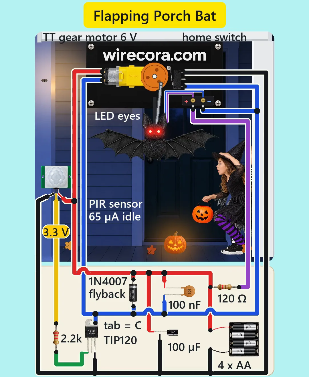
Parts
- HC-SR501 PIR motion sensor (4.5 to 20 V supply, about 65 uA while waiting; OUT gives 3.3 V while it has seen motion; pins GND, OUT, VCC from the left with the dome facing you; a jumper for L or H mode and two trimmers, time and sensitivity)
- TIP120 Darlington transistor, TO-220 (B, C, E from the left with the printed face toward you; the metal tab is the collector; 60 V, 5 A, gain at least 1000)
- TT gear motor, 3 to 6 V, 1:48 gearbox (about 0.15 A with no load, 1.5 A if stalled at 6 V, 0.8 kg·cm stall torque at 6 V; not polarised)
- Roller lever microswitch, Omron SS-5GL2 type, 5 A resistive at 30 V DC (terminals C, NO, NC: only C and NC are used; go by the marks on your own switch)
- 1N4007 diode across the motor (flyback; 1000 V, 1 A)
- Resistors, 1/4 W: 2.2k (sensor OUT to the TIP120 base) and 120 ohm (for the eyes)
- Two red 5 mm LEDs for the eyes, wired in series
- 100 uF 25 V electrolytic capacitor across the battery, and a 100 nF ceramic capacitor marked 104 across the motor
- 4 x AA battery holder (6 V) and four fresh alkaline AA cells
- The prop: a black bat of about 90 cm (36 in) wingspan with light wings (thin fabric on thin rods, about 8 g each) hinged at the shoulders; a mounting plate under the porch roof; a crank disc on the motor shaft with a cam lobe about 50 degrees wide on its rim; a rod from the crank pin down to a yoke that slides in a vertical guide behind the bat's head; and two short levers (about 1.7 cm) that turn each wing about its shoulder hinge, their pins riding in a slot in the yoke. A crank radius of about 1 cm gives a 2 cm stroke, which swings the wings about 90 degrees: from folded down along the body to just above level
How it is wired
- Holder red lead (+) is the +6 V line, holder black lead (-) is GND. One supply, one ground for everything. Put the 100 uF across the two at the board: long leg on +6 V, stripe leg on GND.
- +6 V to the sensor's VCC pin, one motor terminal, the band (cathode) end of the 1N4007 and one end of the 120 ohm.
- GND to the sensor's GND pin, the TIP120 emitter (right leg) and the microswitch terminal marked NC.
- Sensor OUT (middle pin) through the 2.2k to the TIP120 base (left leg). No resistor from base to ground is needed: the sensor's output is a push-pull output that sits at about 0 V when idle, and the TIP120 has its own base-emitter resistors inside.
- The motor's other terminal to the TIP120 collector. The Short wires it at the metal tab, which is the same as the middle leg; use either one. The plain (anode) end of the 1N4007 goes here too, so the diode sits across the motor with its band toward +6 V.
- Microswitch terminal C (COM) to the collector as well. NO stays unused. So the switch sits in parallel with the transistor: the motor runs while the TIP120 is on OR the switch is closed.
- Eyes: the free end of the 120 ohm to the first LED's long leg, its short leg to the second LED's long leg, the second LED's short leg to the collector. In the Short this pair runs as one twin lead (+ and -) from a small screw block on the plate down behind the bat's ear into the head. The eyes light only while the motor runs.
- The 100 nF goes across the motor. The Short draws it on the board; in a real build solder it straight onto the motor's two tabs, where it stops brush noise best.
- Mount the microswitch so its roller rides the crank disc's rim and the cam lobe presses it open only when the wings are folded. If the wings beat the wrong way round for your linkage, swap the two motor wires.
- HC-SR501 settings: jumper on L (single trigger), time trimmer nearly fully anticlockwise (the shortest hold, about 2.6 s in the Short; boards vary from about 1 to 3 s), sensitivity in the middle. Aim it down at the walkway people use, so the bat hanging above is outside its view (the bat has no body heat anyway).
How it works
- At rest the wings are folded, the cam lobe holds the microswitch open, the sensor's OUT is at 0 V and the TIP120 is off: nothing moves, and the whole circuit draws only the sensor's 65 uA.
- A visitor walks into the sensor's view. Its OUT goes to 3.3 V and pushes about 0.95 mA through the 2.2k into the TIP120 base. With a gain of at least 1000 the transistor turns on and starts the motor; the start current is held to about 0.6 to 1.1 A by the base drive and the cells.
- About 80 ms later the crank has turned off the lobe, the microswitch's NC contact closes and joins the motor's minus side straight to GND, alongside the transistor. From then on the switch carries the motor at almost the full 6 V, and the transistor only carries it again for about 56 ms once per turn as the lobe passes under the roller.
- Each turn of the crank pushes the rod and yoke up and down once, and the two levers turn that into one full wing beat: from folded, up through level and spread wide, to just above level and back. At about 150 rpm that is about 2 to 2.5 beats a second. The Short shows seven beats.
- After about 2.6 s the sensor's timer ends and OUT drops to 0 V, so the TIP120 turns off. The wings are usually mid-beat, but the closed microswitch keeps the motor running until the cam lobe reaches the roller at the folded position and opens it. The motor then coasts about 12 to 24 degrees and stops on the lobe, which is about 50 degrees wide, so the wings always park folded. If you switch it on with the wings open, it runs to folded by itself and stops.
- In L mode the HC-SR501 ignores motion for about 2.5 s after OUT goes low, then waits for the next visitor. Someone who stays in view gets another flap after that.
- The eyes sit across the motor, from +6 V through the 120 ohm to the motor's minus side, so they glow exactly while the motor runs: about 18 mA through the switch (23 mA at worst on fresh cells), under the LEDs' 30 mA.
- When the motor stops, the 1N4007 catches the coil's voltage kick, so the transistor and the switch never see a spike. The 100 nF keeps the motor's brush sparks off the 6 V line so they cannot false-trigger the sensor.
- Currents: the motor about 0.5 A running (0.2 kg·cm average load against its 0.8 kg·cm stall torque), well under the TIP120's 5 A, the switch's 5 A and the diode's 1 A. The TIP120 warms for only fractions of a second at a time (at worst about 2.25 W for 80 ms at the start), so it needs no heatsink.
- Batteries: about 0.4 mAh per scare and 65 uA while waiting, so 200 visitors use about 83 mAh of a set of AA cells' roughly 2,500 mAh: one fresh set lasts the season.
- Why no Arduino and no relay: the sensor already has a timer, and the switch on the crank does the parking. Why not a wiper motor like big store props: it pulls 2 to 4 A and needs a big supply; light fabric wings need only a TT motor.
What the video simplifies
- The HC-SR501 has no light of its own. The 0 V / 3.3 V tag on its yellow output wire is drawn so you can see when it fires.
- The sensor is drawn facing the camera and about three times its real size so its pins show; a real one points down at the walkway.
- The bat hangs about 1.5 m nearer the camera than the kids and the door, so it looks bigger than them. The plate, the motor, the crank, the switch and the board are drawn several times larger than the bat, and the battery holder is drawn a bit small.
- The 100 nF capacitor is drawn on the board; in a build it belongs on the motor's tabs.
- The microswitch is drawn without its C, NO and NC marks and its roller stays still; on a real one the lever lifts as the lobe passes. Use the marks on your own switch.
- The TIP120's B, C and E letters are not printed under its legs in the Short for lack of room; they are on this page.
- The motor current (0.5 A), the 8 g wings, the transistor's drop, the 2.6 s timer setting, where the sensor's view starts and the coast after power-off are assumed or typical values. The drawn crank turns at about 148 rpm; the seller (Adafruit) measured 250 rpm with no load at 6 V, so a real bat may beat a little faster.
- While the microswitch carries the motor, the sensor's OUT feeds about 1.2 mA into the base instead of 0.95 mA. That only pulls its 3.3 V down a little and does no harm.
- Tired cells can dip the 6 V line under the sensor's 4.5 V minimum when the motor starts (the 100 uF does not hold it up for long). Use fresh cells.
- The wing cloth's flutter is drawn; the wing roots and tips stay exactly where the linkage puts them. The kids' reaction is staged, the moth and the leaves are scene life, and all the sounds are synthesised.
- This circuit was checked by calculation, an ngspice simulation and the datasheets, not built.
Everything runs on four AA cells (6 V DC); no mains wiring. The crank, rod and levers can pinch fingers: cover the mechanism and take a cell out before you reach into it. Hang the bat at least 2 m up, out of reach, and fix it and its plate firmly so nothing can fall on a visitor. Keep the bat and its wings away from real candles: use an LED light in the pumpkin. Put the board and the battery holder in a box out of the rain, and never short the battery leads: AA cells can get hot. Give the sensor 30 to 60 s to settle after you put the cells in.
Build it yourself
The wiring board has no PIR sensor, gear motor, home switch or linkage yet, so this one cannot be opened on it. Start with the guided first build on the wiring board, where a circuit really works as you wire it, then try the ready-made ones.
Your first circuit, step by stepAll circuits from the Shorts
Stuck, or built it?
Ask about this circuit or show your build in the Wirecora Discord. Questions get an answer every day.