Foot pedal motor switch with a 5 V relay and a 12 V motor
Step on the pedal and the 12 V motor runs and the green RUN lamp lights. Lift your foot and the motor coasts to a stop, and the lamp fades out as it slows. The pedal never carries the motor's current: it only switches the relay's coil, and the relay switches the motor.
From the Short Step On The Pedal And The Motor Runs | Foot Switch With A 5V Relay (515K views, posted 17 October 2026). Opens on YouTube.
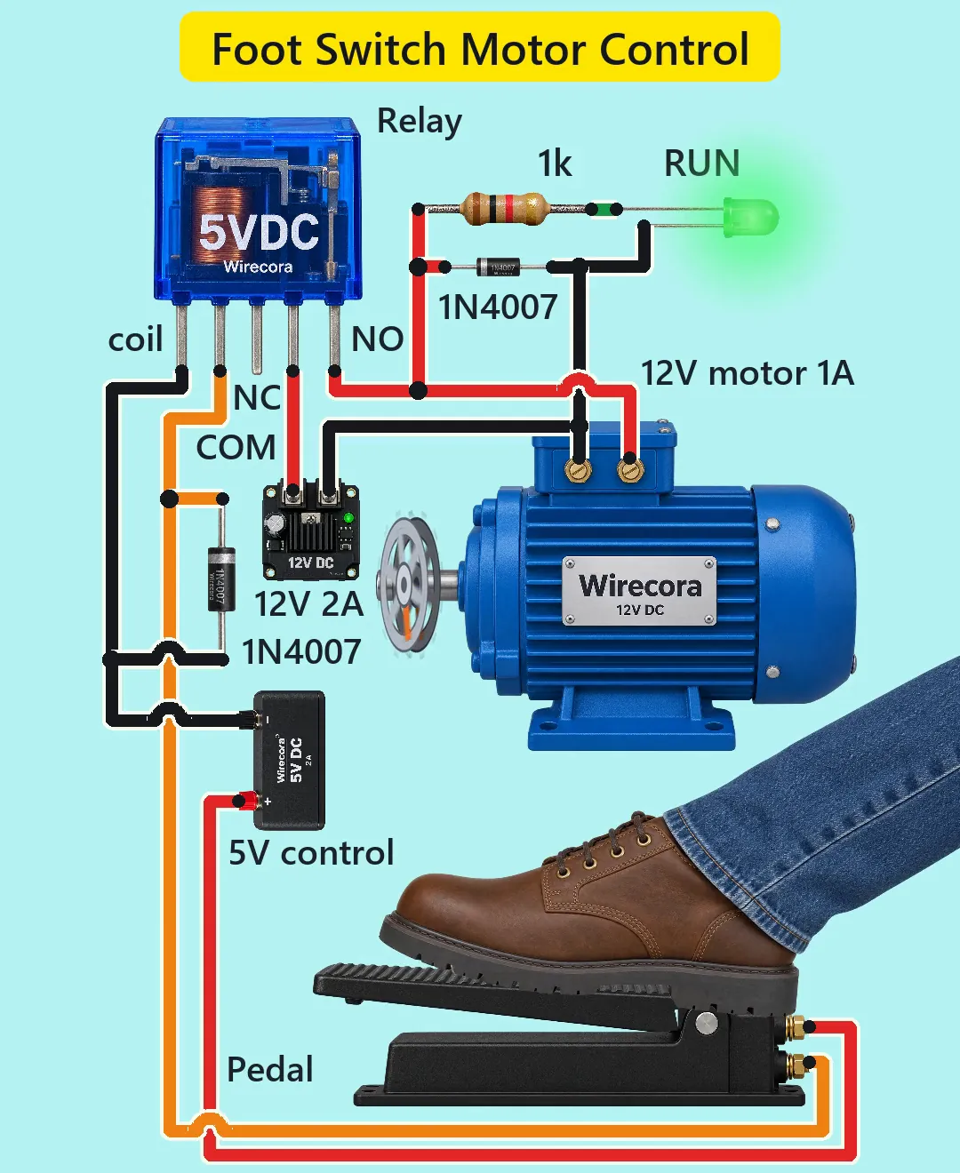
Parts
- Foot switch, normally open (closed only while you press it). If yours has three terminals, use COM and NO
- 5 V relay, SRD-05VDC-SL-C or similar: 70 ohm coil (about 71 mA at 5 V), five pins: two coil pins, COM, NO, NC. Its datasheet rates the contacts 7 A at 28 V DC, and 3 A at 28 V DC for a motor or other coil (the case print may say 10 A)
- 12 V DC brushed motor, about 1 A running and about 3 A for a moment at start
- 2 x 1N4007 diode (the band is the cathode)
- Green 5 mm LED (the long leg is the anode) and a 1k resistor, 1/4 W (bands brown, black, red, gold)
- Regulated 5 V supply for the control side (the Short uses a 5 V 2 A one; the coil needs only 71 mA)
- 12 V 2 A supply for the motor
- A 2 A slow-blow fuse and holder for the 12 V plus wire (not drawn in the Short; add it)
How it is wired
- Control side, 5 V: 5 V supply plus to one pedal terminal. The other pedal terminal to one coil pin of the relay. The other coil pin to 5 V supply minus.
- First 1N4007 across the relay coil: band (cathode) on the coil pin wired to the pedal, plain end on the coil pin wired to 5 V minus.
- Motor side, 12 V: 12 V supply plus through the fuse (close to the supply) to the relay's COM. Relay NO to motor plus. Motor minus to 12 V supply minus. Relay NC stays free.
- Second 1N4007 across the motor: band on motor plus, plain end on motor minus.
- The 1k from motor plus to the LED's long leg; the LED's short leg to motor minus. The lamp shows when the motor has voltage.
- The two sides share no wire: the relay is the only link between them.
- The Short draws the relay's pins in one row (coil, coil, NC, COM, NO), and no real relay looks like that. On an SRD-05VDC-SL-C, COM is the middle pin at one end with the two coil pins either side of it, and NO and NC are the two pins at the other end. Go by the diagram printed on the relay, or check with a meter: about 70 ohm between the two coil pins, 0 ohm between COM and NC with no power, and no connection between COM and NO.
How it works
- Pressing the pedal puts 5 V on the coil: 5 V / 70 ohm = 71 mA. Within 10 ms the relay pulls in, COM joins NO and the motor gets 12 V.
- That is why there is a relay: the pedal and its cable carry only 71 mA at 5 V, and the motor's amps run only through the relay's contacts.
- The LED gets (12 - 2.0) / 1k = 10 mA while the motor runs; the 1k takes 0.1 W of its 1/4 W.
- Lifting your foot cuts the coil. A coil tries to keep its current flowing, which would make a high voltage spike and spark the pedal contact. The first 1N4007 gives that current a path round the coil. It makes the relay let go a little slower: about 10 to 20 ms instead of the 5 ms or less the datasheet gives without a diode.
- The motor is a coil too. When NO opens, the second 1N4007 carries the motor's current for about half a millisecond (about 0.9 A, inside the diode's 1 A rating and 30 A surge), so the relay contacts do not arc.
- After that the coasting motor works as a generator: at full speed this motor makes about 8 V, with the same polarity as before. So the lamp does not snap off; it fades over about 1.25 s as the motor slows. The diode across the motor stays off while it coasts.
- Currents: running, the 12 V supply gives about 1.01 A of its 2 A. At start the motor takes about 3 A for a moment, so a 2 A supply sags or limits for the first tenth of a second. The relay closes on that start current and opens about 1 A, inside its 3 A rating for a motor. A slow-blow fuse lets the short start current through.
What the video simplifies
- The viral original switches a three-phase mains motor with a contactor and an overload relay. This is the same idea at safe low voltage.
- The motor is drawn like an industrial induction motor, but the circuit is for a 12 V DC brushed motor. An AC induction motor will not run from it.
- The motor's 1 A running and 3 A start current are assumed, and so is its 8 V at full speed. A bigger motor needs a bigger supply and a relay rated for its start current.
- The relay's pins are drawn in one row; follow the names and the real layout in the wiring list above.
- No fuse is drawn. Put a 2 A slow-blow fuse in the 12 V plus wire of a real build.
- The flywheel turns slowly (about 200 rpm) so you can follow its spokes. The spin-up, coast-down and lamp fade are timed to fit 6 s; a real motor with a load stops faster and its lamp fades faster.
- The relay's moving part is not animated; a flash marks the moment it switches.
- The relay, diodes, LED and supplies are drawn much larger than the motor, pedal and boot.
- The sounds are synthesised.
- This circuit was checked by calculation and against the datasheets, not built.
Everything runs on 5 V and 12 V DC. Do not copy the viral original's mains wiring: a mains motor needs a contactor, an overload relay and an electrician. This small relay's DC ratings are given at 28 V, so keep it to low-voltage DC like this. Put a fuse in the 12 V plus wire. A motor with a flywheel or a load keeps turning after you lift your foot, so keep fingers, hair and loose clothes away from the shaft, and fix the motor down so its start does not jerk it off the bench.
Build it yourself
The wiring board has a 5 V relay module, a push button and a small 6 V motor, but no bare relay, foot switch or 12 V motor, so this one cannot be opened on it as drawn. Start with the guided first build on the wiring board, where a circuit really works as you wire it, then try the ready-made ones.
Your first circuit, step by stepAll circuits from the Shorts
Stuck, or built it?
Ask about this circuit or show your build in the Wirecora Discord. Questions get an answer every day.