Motion-activated garden sprinkler with a PIR sensor, an Arduino Nano and a 12 V valve
At night, when something warm moves in front of the sensor, the valve opens and a water-driven sprinkler head sweeps the garden bed for 3 seconds. Then the valve shuts and the circuit waits 2.5 seconds before it can fire again. In daylight it does nothing, because the light sensor says it is not dark.
From the Short A Raccoon Sneaks Into the Garden and a Water Jet Chases It Out (posted 29 October 2026). Opens on YouTube.
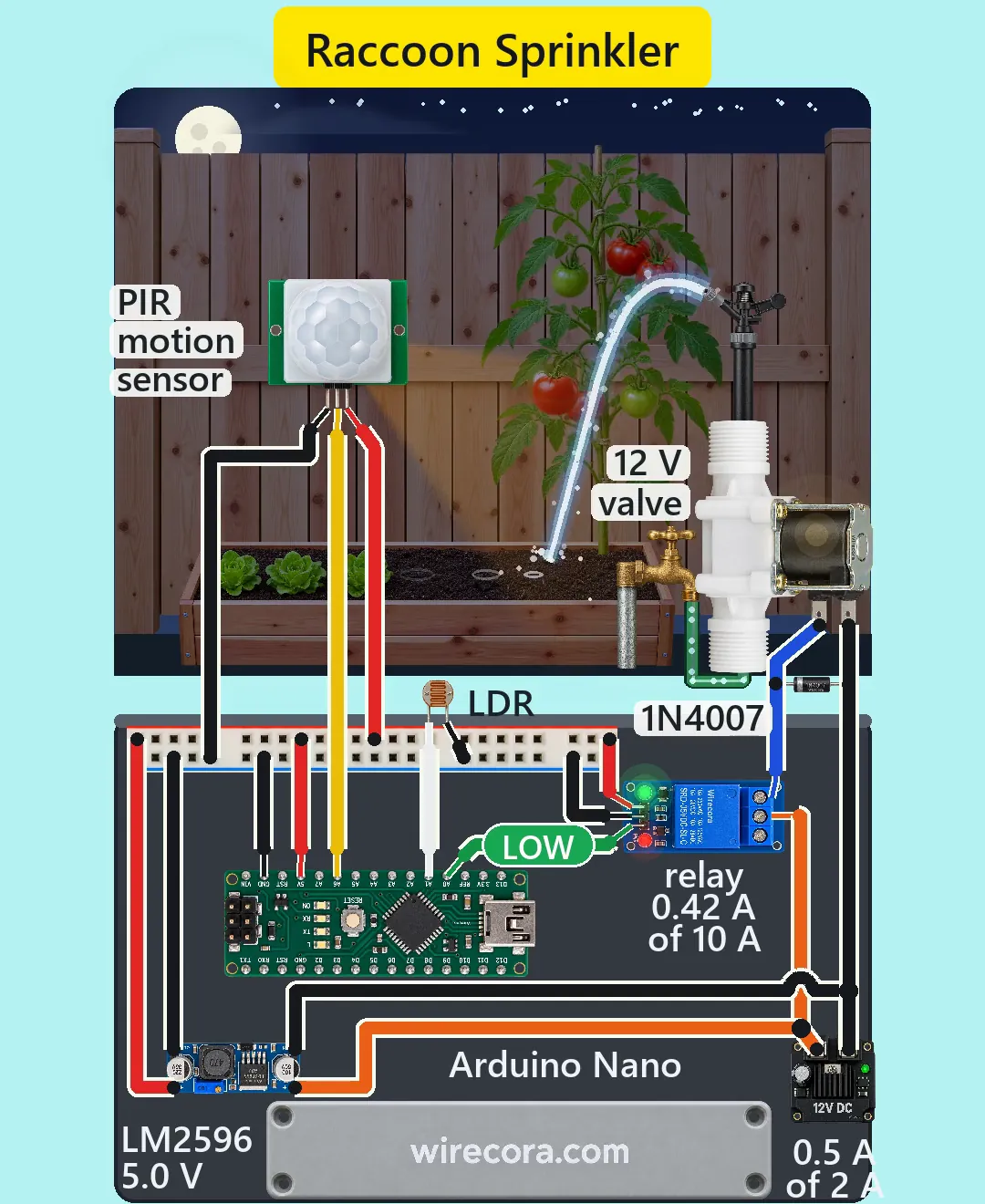
Parts
- 12 V 2 A DC power supply (the Short draws about 0.5 A of it)
- LM2596 buck converter module, input 3.5 to 40 V, 1.5 A, with its trimmer set to 5.0 V before you connect anything else
- Arduino Nano (powered on its 5V pin; nothing goes on VIN)
- HC-SR501 PIR motion sensor (pins GND, OUT, VCC; OUT is 3.3 V when it sees motion). Jumper on L (single trigger), time trimmer turned fully anticlockwise (about 3 s hold)
- 5 V 1-channel relay module, active LOW (the relay is on while IN is LOW), contacts rated 10 A at 30 V DC
- 12 V normally closed solenoid valve for water, about 0.42 A (some valves 0.32 A), opens above about 3 psi (0.02 MPa) and is rated to 0.8 MPa (116 psi). Valves have a flow arrow: inlet from the tap
- 1N4007 diode across the valve (the flyback diode)
- GL5528 LDR (light-dependent resistor), 5 mm
- Half-size breadboard, used for its two power rails only (5 V on the plus rail, ground on the minus rail), and jumper wires
- A water-driven sprinkler head on a short hose from the valve outlet, and a tap with a hose to the valve inlet
- A weatherproof box for the electronics. The sensor looks out through a hole or window, and so does the LDR
- Optional, not drawn: a 10 k resistor from A1 to 5 V to fix the dusk level more exactly
How it is wired
- Set the LM2596 to 5.0 V first: connect the supply to its IN pads, put a multimeter on its OUT pads and turn the trimmer until it reads 5.0 V. Then wire the rest.
- Supply plus (+12 V) to the relay's COM screw and to the LM2596 IN+ pad.
- Supply minus to the valve's first terminal (it has no polarity), and to the LM2596 IN- pad. IN- and OUT- are joined inside the module, so this is one ground.
- LM2596 OUT- to the minus rail of the breadboard. LM2596 OUT+ (5.0 V) to the plus rail.
- Nano: 5V pin to the plus rail, GND pin to the minus rail. Leave VIN empty: the 5 V comes in on the 5V pin, not through the Nano's own regulator.
- PIR: GND to the minus rail, VCC to the plus rail, OUT to Nano A6. A6 is an analog input only, which is fine: the sketch reads it with analogRead.
- Relay module: VCC to the plus rail, GND to the minus rail, IN to Nano A0 (the sketch uses A0 as a digital output).
- Relay NO screw to the valve's second terminal. Leave NC empty.
- 1N4007 across the valve: its band (cathode) on the valve terminal that goes to the relay's NO, its plain end (anode) on the valve terminal that goes to supply minus.
- LDR: one lead to Nano A1, the other lead to the minus rail. An LDR has no polarity. The sketch turns on the Nano's internal pull-up on A1, so no resistor is needed.
- Plumb the tap to the valve inlet (follow the arrow), and the outlet to the sprinkler head. Keep the tap open: the valve holds the pressure.
How it works
- The HC-SR501 senses the change in infrared from something warm that moves. While it sees motion its OUT pin is 3.3 V, which the Nano reads on A6 as about 675 out of 1023. The sketch treats anything above 400 as motion.
- The LDR and the Nano's internal pull-up (about 20 to 50 k) form a voltage divider on A1. In the dark the LDR is a large resistance, so A1 reads high: about 836 at moonlight (0.2 lux). By day it is a small resistance and A1 reads about 27. The sketch treats above 500 as night. That switch-over sits at about 2.6 lux (between 1.4 and 6.7 lux, depending on the chip's pull-up), which is deep dusk. A 10 k resistor from A1 to 5 V would pin it down more exactly.
- When it is night and there is motion, the sketch writes A0 LOW. The relay module turns on when IN is LOW, and its COM-to-NO contact joins the valve's second terminal to the 12 V plus. The valve coil now has the full 12 V and the valve opens.
- The sketch waits 3 seconds (SPRAY_MS = 3000), writes A0 HIGH, and the relay lets go. It then waits another 2.5 seconds (REST_MS = 2500) before it reads the sensors again, so a new burst cannot start in that gap.
- The first line of setup() writes HIGH to A0 before the pin becomes an output. The relay module is active LOW, so this keeps the valve shut at power-up. After that setup() waits 60 seconds, because the HC-SR501 needs 30 to 60 seconds to settle after it is powered.
- When the relay lets go, the valve coil (a few tenths of an amp) pushes current into the diode. The 1N4007 clamps the switched terminal to about 1 V below ground, so the relay contacts do not see a large voltage spike. The relay module also has its own diode across its own coil.
- The sensor's own timing matters. After it triggers, the HC-SR501's OUT stays HIGH for its hold time (about 3 s at minimum) and then it is blocked for about 2.5 s. If you turn the time trimmer up so the hold is longer than about 5.5 s, OUT is still HIGH when the sketch finishes its rest, and the valve fires a second burst straight away.
- Numbers: the 5 V side draws about 0.12 A (relay coil 71 mA, Nano, PIR and LEDs), so the LM2596 carries about 0.12 A of its 1.5 A and takes about 0.06 A from the 12 V supply. The valve takes 0.42 A. Together that is about 0.5 A of the supply's 2 A. The relay contacts carry 0.42 A of their 10 A. The valve coil is about 29 ohms, so it dissipates about 5 W for the 3 seconds it is on.
- Water: one burst of 3 s at 10 to 20 L/min is about 0.5 to 1 L (2 to 4 cups). The flow is an estimate. Normal tap pressure is 40 to 80 psi (275 to 550 kPa), far above the 3 psi the valve needs.
The code: garden_sprinkler.ino
The Arduino code for this circuit is in the Wirecora Discord, in the channel #arduino-code (owner’s choice, 14 October 2026: the code lives where you can ask about it). It is a plain .ino file you can download there.
The sketch the Short was animated from, step by step in a simulation of the sensor timing; it has not been run on a real board yet. Change SPRAY_MS and REST_MS for a longer or shorter burst. Change NIGHT to move the dusk level: a higher number needs a darker garden. Set the HC-SR501 jumper to L and its time trimmer fully anticlockwise, as the page says.
What the video simplifies
- The jet's range is turned down to fit the garden bed. A real water-driven head at tap pressure throws several metres.
- The PIR's view is drawn as a glowing wedge. Infrared is invisible.
- The yellow glow around the solenoid when the valve is open and the light dashes running up the hose are drawing devices. A coil does not glow and you cannot see water inside an opaque hose.
- The hold time (3 s) and block time (2.5 s) of the sensor, the valve's opening and closing times, the flow rate and the module currents are typical values, not measured ones.
- The scales are mixed. The PIR is drawn about 5 times, the valve about 3 times and the electronics several times larger than the garden around them. The 12 V supply is drawn smaller than a real adapter, and the LM2596 is drawn smaller than the Nano.
- The control box is drawn open so you can see inside. A real one is closed, with a hole or window for the sensor, and the LDR must look out at the sky too. If the LDR is shut inside the box, A1 always reads dark and the night test is always true.
- The raccoon's bolt is staged: it is only startled by the spray, the jet passes it, and a real animal runs faster. Raccoons also get used to a sprinkler, so move it every few days.
- The sounds are synthesised. The video is a loop of one cycle: a second raccoon walks in during the rest time.
- This circuit was checked by simulation and against the datasheets, not built. The sketch has not been run on a real board yet.
Everything in the circuit runs on 12 V DC or 5 V DC from a certified adapter, and you do no mains wiring. Water and electricity still need care outdoors: put the supply, the Nano, the relay and the breadboard in a closed, weatherproof box and keep the box out of the spray. The adapter itself plugs into the mains, so keep its plug indoors or in a proper outdoor-rated enclosure. Drain the valve and the hose before frost, and aim the sprinkler where it will not hit people or passing pets.
Build it yourself
The wiring board has a 5 V relay module, a 12 V solenoid valve, a 12 V supply, the 1N4007 and a light sensor (LDR). It has an Arduino Uno but no Nano, no PIR sensor and no LM2596 module, and it cannot run an Arduino program yet, so this one cannot be opened on it. Start with the guided first build on the wiring board, where a circuit really works as you wire it, then try the ready-made ones.
Your first circuit, step by stepAll circuits from the Shorts
Stuck, or built it?
Ask about this circuit or show your build in the Wirecora Discord. Questions get an answer every day.