Helmet brake light with an Arduino Nano, an MPU6050 accelerometer and an 8-LED WS2812B stick
While you ride, the light bar on the back of your helmet glows a soft red. Squeeze the brakes and it jumps to bright red within about a quarter of a second, so the driver behind sees you slowing down. When you stop slowing it stays bright 0.6 s longer, then settles back to the glow. A pothole bump or a climb does not set it off.
From the Short This Helmet Light Turns Bright Red When You Brake (posted 26 October 2026). Opens on YouTube.
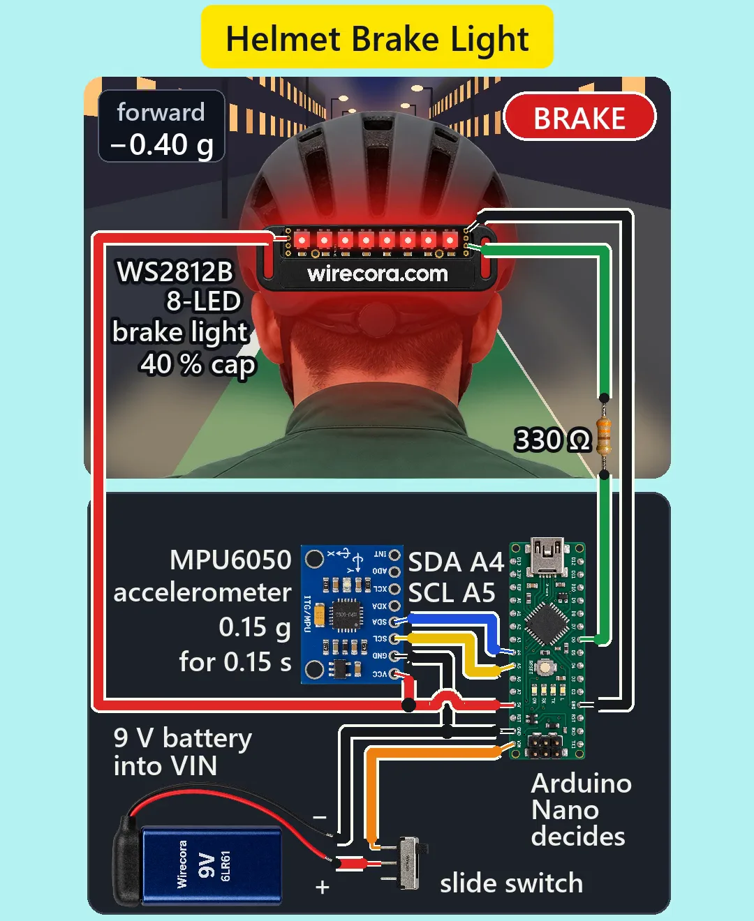
Parts
- Arduino Nano, 5 V, 16 MHz (an Uno works the same with the same pin numbers)
- GY-521 board with the MPU6050 accelerometer (VCC 3 to 5 V, it has its own 3.3 V regulator; header VCC, GND, SCL, SDA, XDA, XCL, AD0, INT; address 0x68 with AD0 left open)
- 8-LED WS2812B stick (input pads GND, DIN, 5VDC, GND; the pads at the other end are GND, DOUT, 5VDC, GND, and its 5VDC is the same copper as the input 5VDC; 4 to 7 V)
- 330 ohm resistor, 1/4 W, for the stick's data line (bands orange, orange, brown, gold)
- 9 V battery (PP3) with a snap lead: red = +, black = -
- Small slide switch (SPDT, 0.5 A; only the middle pin and one end pin are used)
- Thin three-wire lead, about 60 cm, from the box to the helmet, and hook-up wire
- A small box that clips to the back of your jersey or a backpack strap, and a clip or strap to hold the LED stick low on the back of the helmet
How it is wired
- Battery + (red) to the slide switch's middle pin. The switch's end pin to the Nano's VIN pin. VIN is made for 7 to 12 V and goes through the Nano's own 5 V regulator.
- Battery - (black) to a Nano GND pin. That is the ground for every part.
- Nano 5V pin to the GY-521's VCC and to the stick's 5VDC pad. Here the 5V pin is the output of the Nano's regulator: nothing else feeds it.
- GY-521 GND and the stick's GND pad to the Nano's GND (the Nano has two GND pins; they are joined on the board, so either one works).
- GY-521 SDA to Nano A4, GY-521 SCL to Nano A5. Leave XDA, XCL, AD0 and INT free.
- Nano D6 to the 330 ohm resistor, the resistor's other end to the stick's DIN pad. In the Short it sits in the lead over the shoulder; you can just as well solder it right at the DIN pad, which is where Adafruit suggests.
- Leave the stick's DOUT pad free. Leave VIN as the only power input: do not plug in USB while the battery is switched on.
- Mount the box upright on your back with the GY-521's chip side facing backward (away from you). If you mount it facing your back, forward reads the other way: remove the minus sign in forwardG().
How it works
- The MPU6050 measures acceleration. The sketch reads only the axis that points forward along the bike, about 90 times a second, through the MPU's own 44 Hz filter.
- It keeps two averages: a fast one (about 50 ms) and a slow one (about 4 s) that learns your normal riding, including a steady hill or the way you lean. Slowing is the fast value minus the slow one, so a climb or a lean drifts away and only a sudden change counts.
- If you slow by more than 0.15 g and that lasts 150 ms, the light switches from the 6 % running glow (red 16 of 255) to 40 % red (102 of 255). A pothole jolt lasts a few hundredths of a second: in the simulation a 1 g jolt of 40 ms, or even 2 g, stays dark.
- In the Short the rider brakes at 0.40 g from 25 km/h: the light comes on about 0.25 s after the slowing starts and stays on the whole time you slow. While braking the slow average is frozen, so a long brake is not learned away.
- 0.6 s after the slowing drops under 0.08 g it goes back to the glow. It is never on for more than 5 s in one go: after that it takes the current reading as the new normal. That stops a steep downhill or a new riding position from holding it on.
- Why the sensor is on your back, not in the helmet: a nod of your head would tilt a helmet sensor and look like braking. Your back moves with the bike.
- Power: about 41 mA at the glow and about 90 mA while braking (8 LEDs x 18 mA x 40 %, plus the Nano and the sensor board). The Nano's regulator turns (9 - 5) V x 0.09 A = 0.36 W into heat, fine without a heatsink. A 9 V battery lasts roughly 8 hours of riding.
- The 40 % cap matters: full white on all 8 LEDs would take about 0.4 A, far too much for the Nano's regulator. The sketch never sets green or blue.
- No big capacitor: Adafruit's 500 to 1000 uF is for NeoPixels hung straight on a large power supply. These 8 LEDs, capped at about 58 mA, run from the Nano's own regulator and its output capacitors. No resistors on the LEDs either: WS2812B LEDs set their own current; the 330 ohm is only in the data line.
- No flyback diode or fuse: there is no motor, relay or coil, and a 9 V battery through a 0.5 A switch carries 0.09 A. The battery snap fits only one way, so no reverse-polarity diode is needed.
- Signal levels: D6 drives DIN at about 5 V against the 3.5 V it needs. The GY-521 pulls SDA and SCL up to its own 3.3 V, so a high is about 3.4 V, a little under the 3.5 V the Nano's chip guarantees. It is the usual pairing and works in practice, but it is outside the datasheet figure.
The code: helmet_brake_light.ino
The Arduino code for this circuit is in the Wirecora Discord, in the channel #arduino-code (owner’s choice, 14 October 2026: the code lives where you can ask about it). It is a plain .ino file you can download there.
The sketch the Short was animated from, run step by step in a simulation on the rider in the video; it has not been run on a real board yet. One change for the page: forwardG() turns the reading into a float before the minus sign, so the very end of the range cannot overflow. It needs the Wire library (built in) and Adafruit NeoPixel (Sketch, Include Library, Manage Libraries). The Serial Monitor at 115200 shows the forward reading in g; if braking makes it go up instead of down, remove the minus sign in forwardG().
What the video simplifies
- The LED stick is drawn about 3 times its real size on the helmet, and the red glow on the helmet and shoulders is drawn to show the lit state.
- The electronics box is drawn open and much larger below the rider; in a build it clips to your back and a thin lead runs up to the helmet. The battery is drawn smaller than real next to the Nano.
- The 330 ohm resistor is drawn in the lead over the shoulder; it can also be soldered right at the stick's DIN pad.
- The rider stands still in the frame; only the street moves. The street, the car's headlights (the car is never seen) and the distances are illustration.
- The Nano's and the GY-521's power LEDs are drawn unlit; on real powered boards they glow. The joint dot where the sensor's 5 V wire meets the red 5 V line is drawn black; it is a 5 V joint, not ground.
- It shows that you are slowing, not that you have stopped: once you stand still at a light it goes back to the glow. One very long slowing (over 5 s) also drops back to the glow.
- What it cannot tell apart: rolling onto a descent steeper than about 20 %, or leaning much further forward, reads like slowing and can light it, for 5 s at most. Very gentle slowing (under about 0.14 g) stays at the glow. On a strongly leaning back it reacts less to braking.
- The Nano's 19 mA, the sensor board's 5 mA, the LEDs' idle current, the battery's usable 400 mAh, the jolt sizes and the box riding upright are assumed. All the sounds are synthesised.
- This circuit was checked by simulation and against the datasheets, not built.
Everything runs on one 9 V battery; no mains wiring. This is a second brake light on top of your bike's own rear light, never a replacement, and check your local rules for extra lights on a helmet. Do not plug in USB while the battery is switched on. Keep the box and the lead dry and route the lead so it cannot snag. Never short the battery's snap.
Build it yourself
The wiring board cannot run an Arduino program yet, so this one cannot be opened on it. Start with the guided first build on the wiring board, where a circuit really works as you wire it, then try the ready-made ones.
Your first circuit, step by stepAll circuits from the Shorts
Stuck, or built it?
Ask about this circuit or show your build in the Wirecora Discord. Questions get an answer every day.