Porch jack-in-the-box with an Arduino Nano, an HC-SR04, an MG995 servo and a TT gear motor
Hold your trick-or-treat pail out to the box. When it comes within 20 cm, the crank on the side turns once, the lid flies open and a clown springs up about 24 cm, bobbing on its spring neck. About 3 seconds later it folds back in slowly, the lid drops shut on top of it, and once nothing has been near for a second it waits for the next kid.
From the Short Hold Out Your Candy Pail and This Jack-in-the-Box Pops Out (posted 25 October 2026). Opens on YouTube.
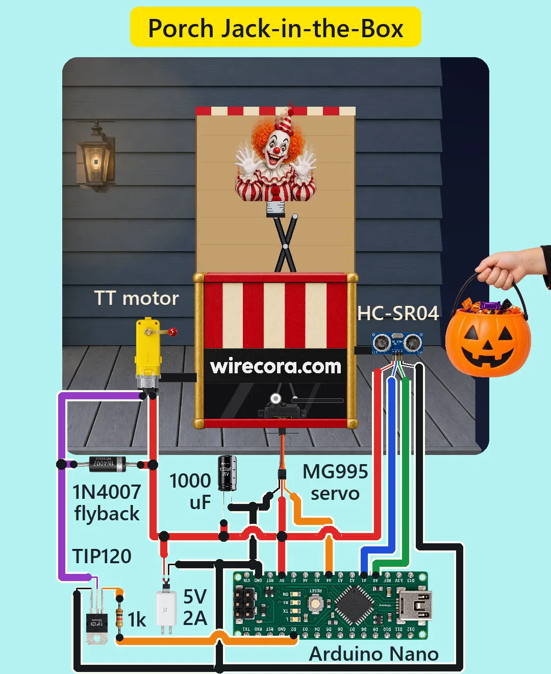
Parts
- Arduino Nano, 5 V
- HC-SR04 ultrasonic distance sensor, 5 V, about 15 mA (pins VCC, TRIG, ECHO, GND from the left, header down)
- MG995 servo (4.8 to 7.2 V; about 8.8 kg·cm at 5 V; stall about 1.5 A; plug brown = GND, red = +, orange = signal)
- TT gear motor, 3 to 6 V, 1:48 gearbox (not polarised), to turn the crank
- TIP120 Darlington transistor, TO-220 (B, C, E from the left with the printed face toward you; the metal tab is the collector)
- 1k resistor, 1/4 W (Nano D2 to the TIP120 base)
- 1N4007 diode across the motor (flyback)
- 1000 uF 25 V electrolytic capacitor at the servo plug
- Regulated 5 V 2 A USB power supply with its cable cut (red = +5 V, black = ground). It must be regulated: the Nano's 5V pin has no regulator in front of it
- Optional: a 100 nF ceramic capacitor (marked 104) soldered across the motor tabs
- The prop: a box about 26 cm wide with a hinged lid and a short stop chain, a three-cell scissor lift (links about 10 cm) driven by the servo horn, a light clown (about 80 g with its spring neck and the top links), and a crank on the motor's output shaft
How it is wired
- Supply red (+5 V) is the +5 V line and supply black is ground. One supply and one ground for everything.
- +5 V to the Nano's 5V pin, the servo's red wire, the HC-SR04 VCC and one motor terminal. Leave VIN unused.
- Ground to a Nano GND pin, the servo's brown wire, the HC-SR04 GND and the TIP120 emitter (right leg).
- 1000 uF right at the servo plug: long leg on the servo's red (+5 V), stripe leg on its brown (ground).
- Servo orange (signal) to Nano A4.
- HC-SR04 TRIG to A1, ECHO to A0. The analog pins A0 to A5 work as ordinary digital pins here.
- The motor's other terminal to the TIP120 collector (the middle leg, or the tab, which is the same).
- Nano D2 through the 1k to the TIP120 base (left leg).
- 1N4007 across the motor: band (cathode) on the +5 V terminal, plain end on the terminal joined to the collector.
- Set the servo horn so write(40) folds the scissor flat and write(104) lifts the clown fully out (the end angles depend on how the horn is clamped). If the crank turns the wrong way, swap the two motor wires.
- Mount the HC-SR04 on the side of the box at pail height, facing the steps.
How it works
- While waiting, the sketch pings the HC-SR04 about every 60 to 90 ms: a 10 microsecond pulse on TRIG, then the echo time on ECHO divided by 58 is the distance in cm. A reading of 0 means no echo and is ignored.
- A reading under 20 cm trips it. D2 goes HIGH for 443 ms: about 3.7 mA flows through the 1k into the TIP120 base, the transistor saturates and the motor gets about 4.2 V (5 V minus the TIP120's 0.8 V drop), within its 3 to 6 V. At about 134 rpm that is exactly one turn of the crank. The crank is only a countdown for show; it winds nothing.
- When D2 goes LOW, the 1N4007 catches the motor's voltage kick so the transistor never sees a spike.
- Then write(104) sends the servo to its top angle. The scissor multiplies the horn's turn into a 24 cm lift in about 0.3 s. The clown's head pushes the lid open, the lid stops on its chain and falls back onto the head, and the spring neck makes the clown bob.
- After 2.8 s the sketch lowers the servo one degree every 15 ms back to 40, about 1 s, and the lid drops shut. Then it waits until nothing has been within 20 cm for a full second before it can trip again, so one pail gets one pop.
- The sketch never pings while the motor or the servo runs, so their electrical noise never reaches a reading.
- Load: the 80 g clown asks about 2.4 kg·cm of the servo at the hardest point (scissor nearly flat), against about 8.8 kg·cm at 5 V.
- Currents: the motor and the servo never run together. The crank phase draws about 0.2 A; the worst case, a servo held at a stall, is about 1.6 A, inside the 2 A supply. Even a jammed crank (about 1.25 A) stays inside the TIP120's, the diode's and the supply's ratings for its 0.44 s, and the TIP120 needs no heatsink (about 0.13 W normally).
- Why a servo and not a real jack-in-the-box spring: a spring pops faster, but it needs a latch and someone to push the clown back in. The servo folds it back by itself for the next kid.
The code: jack_in_the_box.ino
The Arduino code for this circuit is in the Wirecora Discord, in the channel #arduino-code (owner’s choice, 14 October 2026: the code lives where you can ask about it). It is a plain .ino file you can download there.
The sketch the Short was animated from, simulated cycle by cycle against the pail in the video; it has not been run on a real board yet. It uses the Servo library that comes with the Arduino IDE. Adjust DOWN and UP to your horn, and swap the motor wires if the crank turns the wrong way.
What the video simplifies
- The box front has a clear window so the servo and the scissor show; a real prop hides them.
- The servo, the motor, the sensor and the diode are drawn much larger than real (the diode about 14 times), the electronics larger than the porch, and the USB supply smaller than real. The motor strap and the sensor bracket are drawn as plain black bars; they are not wires.
- The HC-SR04 is drawn face-on so its pins show; in a build it faces the steps. Its ping arcs and the dashed distance line are drawn to show what it measures: ultrasound is silent and invisible.
- There is no display in the circuit: the cm reading is drawn beside the sensor so you can see the sketch's own pings, and it reads the pail even while the pail is still off screen.
- The Nano is drawn turned upside down, so its pin names read upside down; the pins are named on this page. The servo is drawn from its side; in a build its horn faces you so the scissor opens in the picture's plane.
- The clown's weight (80 g), the neck spring, the motor's current and spin-up, and the servo's stall current at 5 V (scaled from its 4.8 V figure) are assumed. The rise time comes from the servo's rated speed and torque with that weight.
- The sketch in the video description uses cm / 20 == 0 and a seconds division because YouTube descriptions do not allow the less-than sign; the sketch here uses plain < and does the same thing.
- It pops for anything within 20 cm of the sensor: a pail, a hand or a dog alike.
- The kid's reaction is staged, and all the sounds are synthesised.
- This circuit was checked by simulation and against the datasheets, not built.
Everything runs on a regulated 5 V USB supply; no mains wiring. Never feed the Nano's 5V pin from anything but a regulated 5 V supply, and do not run the servo from the Nano's USB port alone while you program it (unplug the servo or plug in the 5 V supply too). The scissor lift and the lid can pinch fingers: keep hands out of the box while it is powered and unplug it before you reach in. A sudden pop can make a small child step back fast: put the box where nobody can trip or fall off the steps, and keep the cable off the walkway.
Build it yourself
The wiring board cannot run an Arduino program yet, so this one cannot be opened on it. Start with the guided first build on the wiring board, where a circuit really works as you wire it, then try the ready-made ones.
Your first circuit, step by stepAll circuits from the Shorts
Stuck, or built it?
Ask about this circuit or show your build in the Wirecora Discord. Questions get an answer every day.