Metal detector with a CS209A
Slide a kitchen knife onto the search coil and the red LED lights and the buzzer sounds. Take the knife away and both stop. Then a key goes onto the coil and the LED and buzzer come on again.
From the Short Metal Detector Circuit | CS209A IC (178K views, posted 29 September 2026). Opens on YouTube.
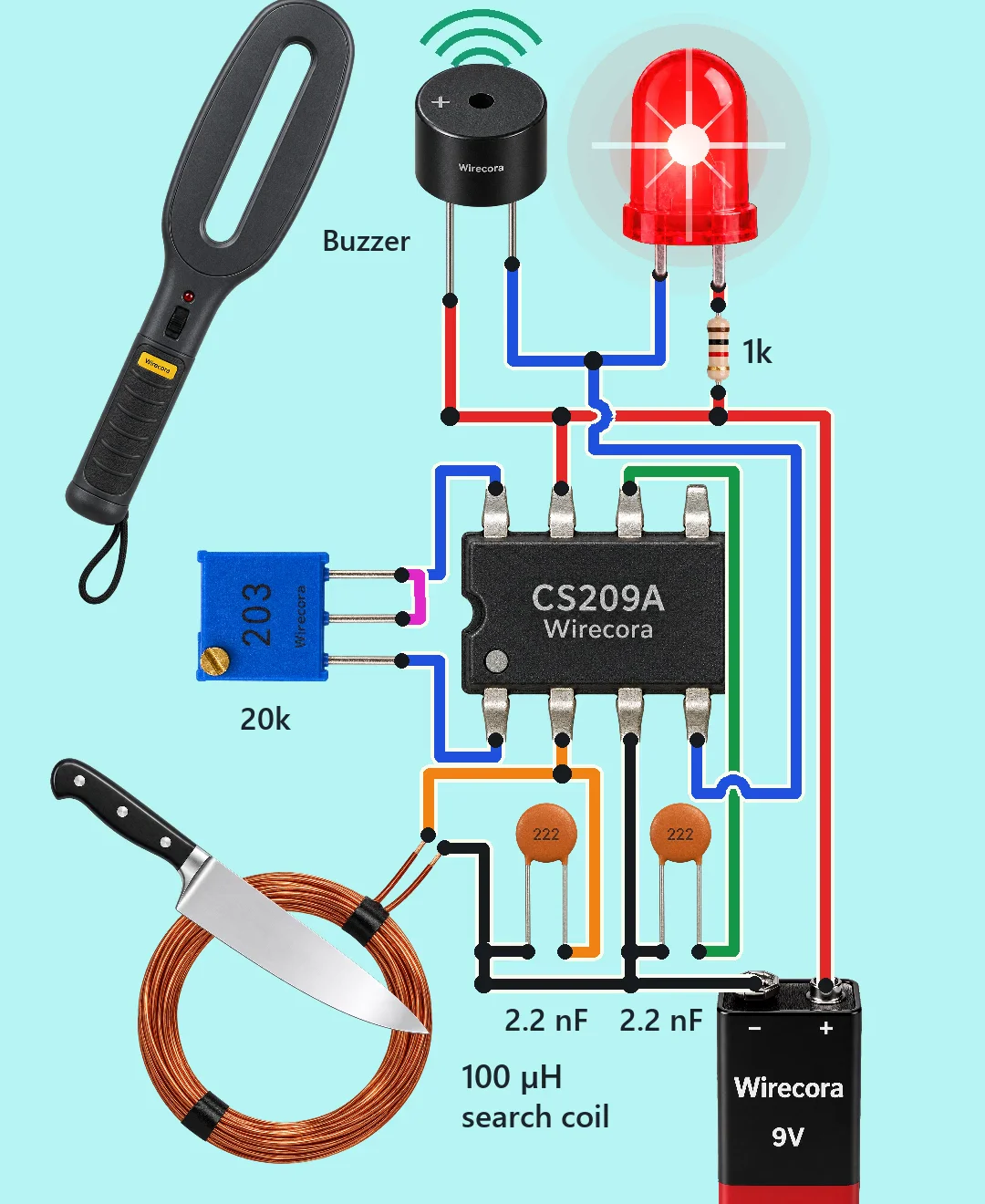
Parts
- CS209A proximity detector IC, DIP-8 (pins: 1 OSC, 2 TANK, 3 GND, 4 OUT1, 5 OUT2, 6 DEMOD, 7 VCC, 8 RF)
- Search coil, about 100 uH: for example about 30 turns of 0.32 mm (28 AWG) enamelled copper wire wound in a ring 64 mm across
- Two 2.2 nF capacitors (printed 222): one for the coil, one for DEMOD. For the coil one, a C0G/NP0 ceramic or a film capacitor keeps the tank steady.
- 20 k trimmer (printed 203), used as a variable resistor
- Red 5 mm LED
- 2.2 k resistor in the LED branch, 1/4 W (bands red, red, red, gold). The Short shows 1 k; see Simplified for why this page uses 2.2 k.
- Active buzzer, 12 mm, rated for 9 V and drawing 15 mA or less (it makes its own tone; check its datasheet)
- 9 V battery
How it is wired
- Battery plus (+9 V) to CS209A pin 7 (VCC), to one end of the 2.2 k resistor and to the buzzer's plus leg.
- Battery minus to pin 3 (GND), to the coil's second lead and to one leg of each 2.2 nF capacitor.
- Pin 2 (TANK) to the coil's first lead and to the other leg of the first 2.2 nF capacitor, so the coil and that capacitor sit side by side between TANK and minus.
- Pin 6 (DEMOD) to the other leg of the second 2.2 nF capacitor.
- Pin 1 (OSC) to one end of the 20 k trimmer; pin 8 (RF) to the other end. The trimmer's wiper is tied to the pin 8 end.
- The other end of the 2.2 k resistor to the LED's anode (long leg); the LED's cathode (short leg) to pin 4 (OUT1).
- Buzzer minus leg to pin 4 (OUT1) too.
- Pin 5 (OUT2) is left unconnected.
How it works
- The CS209A keeps the coil and its 2.2 nF capacitor ringing back and forth at about 339 kHz. This pair is called an LC tank.
- Metal near the coil soaks up some of that energy, so the ringing gets smaller. The chip turns the size of the ringing into a voltage on pin 6, smoothed by the second 2.2 nF capacitor.
- When metal makes that voltage rise above about 1.44 V (a typical value), the chip pulls OUT1 (pin 4) down to minus. It lets go only when the voltage falls back to about 1.2 V, so the output does not flicker at the edge.
- OUT1 only pulls down (an open collector). When it does, current flows from +9 V through the 2.2 k resistor and the LED (about 3 mA) and through the buzzer (12 to 15 mA), so both come on together. That is under 20 mA in total, the most the datasheet guarantees OUT1 can take.
- The 20 k trimmer between OSC and RF sets how sensitive the detector is. Turned too far, the output stays on with no metal, so set it just below that point.
What the video simplifies
- The knife and key are detected while they slide across the coil. A real CS209A senses metal only a few millimetres away. The datasheet gives about 1.1 to 1.4 mm for copper, brass, aluminium and coins, and 2.6 to 3.2 mm for steel. The 7.6 mm (0.3 inch) it mentions is the best case, so a key has to lie on or almost on the coil.
- The detection in the video is worked out from how much metal covers the coil on screen. The real chip switches within milliseconds; the slow slide, the LED fade, the sparkle and the buzzer arcs are drawn for the eye.
- The sound is made for the video: a 2.4 kHz buzzer tone, whooshes and ticks.
- The wand is only a picture and is not wired into the circuit.
- The Short shows a 1 k resistor for the LED. With 1 k the LED takes about 7 mA, and with a 15 mA buzzer OUT1 would carry about 22 mA. That is above the 20 mA the datasheet guarantees. A later check of this circuit chose 2.2 k, which gives about 3 mA in the LED, so the glow is dimmer, and keeps the total under 20 mA. Build it with 2.2 k.
- The datasheet's own example uses a 4300 pF capacitor on the tank and a small resistor in series with TANK whose value it does not give. The video uses 2.2 nF, as the original viral circuit did, and leaves out that resistor.
Everything runs on a 9 V battery, so nothing here can shock you; no power switch is drawn, so unclip the battery when you are done.
Build it yourself
The wiring board has no coils, capacitors or CS209A yet, so this one cannot be opened on it. Start with the guided first build on the wiring board, where a circuit really works as you wire it, then try the ready-made ones.
Your first circuit, step by stepAll circuits from the Shorts
Stuck, or built it?
Ask about this circuit or show your build in the Wirecora Discord. Questions get an answer every day.