PNP transistor checker with an LED
Plug a BC557 into the C, B and E terminals and press TEST: if the transistor works, the green LED lights. Let go and the LED goes out. Pull the transistor out and nothing lights, even with TEST pressed.
From the Short Dead or Alive? BC557 PNP Checker with an LED (142K views, posted 10 October 2026). Opens on YouTube.
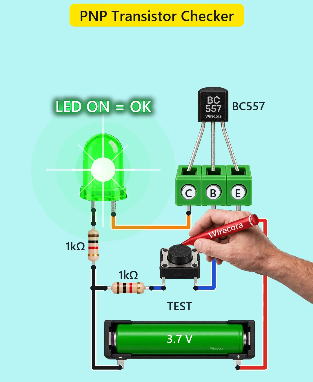
Parts
- BC557 PNP transistor, TO-92 (onsemi part: flat face towards you, legs down: C, B, E from the left)
- 3-way terminal block, marked C, B and E, to plug the transistor into
- Green 5 mm LED (long leg is the anode; a blue or white LED would be very dim on 3.7 V)
- Two 1 k resistors, 5 %, 1/4 W (R1 for the LED, R2 for the base)
- Tactile push button (TEST). Use two legs that the press joins: on a four-leg button, two pairs of legs are always joined.
- 3.7 V Li-ion cell (3.0 V empty, 4.2 V full)
How it is wired
- Cell plus (red wire) to terminal E.
- Terminal C (orange wire) to the LED anode (long leg).
- LED cathode to R1 (1 k); the other end of R1 to cell minus (black wire).
- Terminal B (blue wire) to one leg of the TEST button.
- The other leg of the TEST button (blue wire) to R2 (1 k); the other end of R2 to cell minus.
- The BC557 sits in the block with leg C in terminal C, leg B in terminal B and leg E in terminal E.
How it works
- A PNP transistor turns on when current flows out of its base. The emitter sits at the cell's plus, so the base has to be pulled down towards minus.
- Pressing TEST joins the base to minus through R2. About 3 mA flows out of the base, far more than the BC557 needs, so the transistor switches fully on.
- Now current flows from plus through the emitter and collector, through the LED and R1 to minus: about 1.7 mA, enough to light a green LED.
- Let go of TEST and the base has no path to minus, so no current flows and the LED goes dark. With no transistor the LED stays dark too, and so it does with an NPN whose base is the middle leg (C-B-E or E-B-C), whichever way round it goes in. An NPN with a different pin order can light it, so a dark LED does not by itself prove the part is an NPN.
- This is a go or no-go test, not a gain test: how bright the LED is says nothing about the transistor's gain.
What the video simplifies
- The transistor moves in and out of the block by itself; in real life you push the legs in by hand.
- The LED glow and starburst are drawn: at 1.7 mA a 5 mm LED is far dimmer than shown.
- The hand with the marker, the plunger travel and the sounds are made for the video, and the cell is shown at exactly 3.7 V.
- A BC557 plugged in the wrong way round (emitter and collector swapped) still lights the LED, about as brightly, when TEST is pressed, so LED ON does not prove the legs are in the right order. With collector and base swapped it lights too, more dimly; only base and emitter swapped stays dark.
- If the LED lights without pressing TEST, the part is bad (collector to emitter short) or plugged in wrong.
- Pin orders differ by maker: the onsemi BC557 is C, B, E; NXP and Philips parts are E, B, C. Follow your part's datasheet and put the emitter in E.
Everything runs on one 3.7 V cell and only a few milliamps flow, so nothing gets hot; just keep the cell's bare terminals from touching each other.
Build it yourself
The wiring board has the BC557, an LED, resistors and a push button, but no 3.7 V cell (only a 9 V battery and a 5 V supply), so it can be built there only with the 5 V supply standing in, and the numbers on this page are for 3.7 V. Start with the guided first build on the wiring board, where a circuit really works as you wire it, then try the ready-made ones.
Your first circuit, step by stepAll circuits from the Shorts
Stuck, or built it?
Ask about this circuit or show your build in the Wirecora Discord. Questions get an answer every day.