Police lights with a 555
A finger presses the rocker switch on. The three red LEDs light first, then the red and the blue LEDs take turns, about four swaps a second, like the lights on a police car. Press the switch off and everything goes dark.
From the Short Police Lights Using 555 Timer (213K views, posted 10 October 2026). Opens on YouTube.
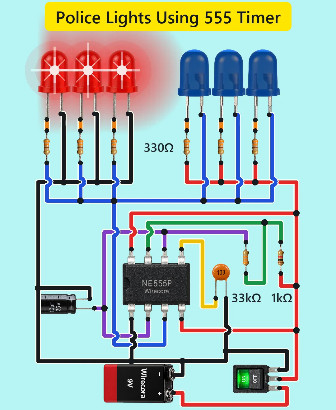
Parts
- NE555P timer, DIP-8
- Three red 5 mm LEDs
- Three blue 5 mm LEDs
- Six 330 ohm resistors, 1/4 W, one for each LED (bands orange, orange, brown, gold)
- 1 k resistor, R1 (bands brown, black, red, gold)
- 33 k resistor, R2 (bands orange, orange, orange, gold)
- 10 uF 25 V electrolytic capacitor, C1 (the stripe is the minus side)
- 10 nF ceramic capacitor (printed 103), C2, on pin 5
- Illuminated rocker switch with three pins: T1 supply in, T2 switched out, T3 lamp return. These are the video's names and the pin order differs between makers, so find the three on your switch from its markings. A 12 V LED-lit rocker glows dimmer at 9 V, and a neon (mains) one will not light at all. Any plain on/off switch in the battery plus lead works the same.
- 9 V PP3 battery
How it is wired
- Battery plus to the rocker's T1.
- Rocker T2 (the switched +9 V) to 555 pin 8 (VCC) and pin 4 (RESET), to one end of R1 (1 k), and to one end of each of the three blue LEDs' 330 ohm resistors.
- Battery minus to the rocker's T3, to 555 pin 1 (GND), to the minus leg of C1 (10 uF), to one leg of C2 (10 nF), and to the cathode (short leg) of each red LED.
- 555 pin 7 (DISCH) to the other end of R1 and to one end of R2 (33 k).
- 555 pin 6 (THRES) and pin 2 (TRIG), which are joined, to the other end of R2 and to the plus leg of C1.
- 555 pin 5 (CONT) to the other leg of C2.
- Each red LED: anode (long leg) to its own 330 ohm resistor; the other end of that resistor to 555 pin 3 (OUT).
- Each blue LED: anode (long leg) to its own 330 ohm resistor (whose other end is on the switched +9 V); the blue LED's cathode (short leg) to 555 pin 3 (OUT).
How it works
- The 555 runs free (an astable): C1 fills through R1 and R2 and empties through R2 into pin 7, so pin 3 goes high and low on its own, about 2.1 times a second. Because R1 is small next to R2, the high and low times are almost the same, about 0.235 s each.
- When pin 3 is high (about 7.4 V), current flows from pin 3 through each 330 ohm resistor and red LED to minus, so the reds light with about 16 mA each (about 18 mA on a fresh battery, still under the LEDs' 30 mA). The blue LEDs then see only about 1.5 V, too little to light.
- When pin 3 is low (a few tenths of a volt), current flows from +9 V through each 330 ohm resistor and blue LED into pin 3, so the blues light with about 16 mA each. The red LEDs then see almost nothing and stay dark.
- Right after switching on, C1 is empty, so the first red flash is longer, about 0.37 s. The 10 nF on pin 5 is there because the 555's datasheet recommends it.
- The 555 gives or takes about 49 mA for one group of three LEDs, far below the 200 mA its datasheet allows, and the whole circuit takes about 61 to 70 mA from the battery.
What the video simplifies
- The glow halos and the star sparkle are drawn for the video; the brightness is only illustrative.
- The rocker's lit red OFF half is a colour cue; a real illuminated rocker's lamp is dark when off. The green ON lamp is wired so it is real.
- The clip restarts each time with C1 empty. After a quick off and on, a real C1 would still hold some charge, so the first red flash would be shorter.
- The soft two-tone sound and the ticks follow the output, but the circuit has no speaker.
- The original video runs the 555 from a 3.7 V cell, below the NE555's 4.5 V minimum; this version uses a 9 V battery and gives every LED its own 330 ohm resistor.
Everything runs on one 9 V battery, so nothing here can shock you; just do not let the battery's snaps touch each other or a bare wire.
Build it yourself
The wiring board has no 555 or capacitors yet, so this one cannot be opened on it. Start with the guided first build on the wiring board, where a circuit really works as you wire it, then try the ready-made ones.
Your first circuit, step by stepAll circuits from the Shorts
Stuck, or built it?
Ask about this circuit or show your build in the Wirecora Discord. Questions get an answer every day.