Arduino radar guard with an HC-SR04 and a servo
An ultrasonic sensor on a servo sweeps from side to side. Put something within 30 cm in front of it: the sweep stops on it, the LCD says WARNING! Object at 15 cm and the buzzer beeps three times. Move the object and the sensor follows it in 5 degree steps. Take it away and the screen says Area is Empty and the sweep starts again.
From the Short Arduino Radar Finds the Block, Locks On and Beeps | HC-SR04 + Servo (posted 23 October 2026). Opens on YouTube.
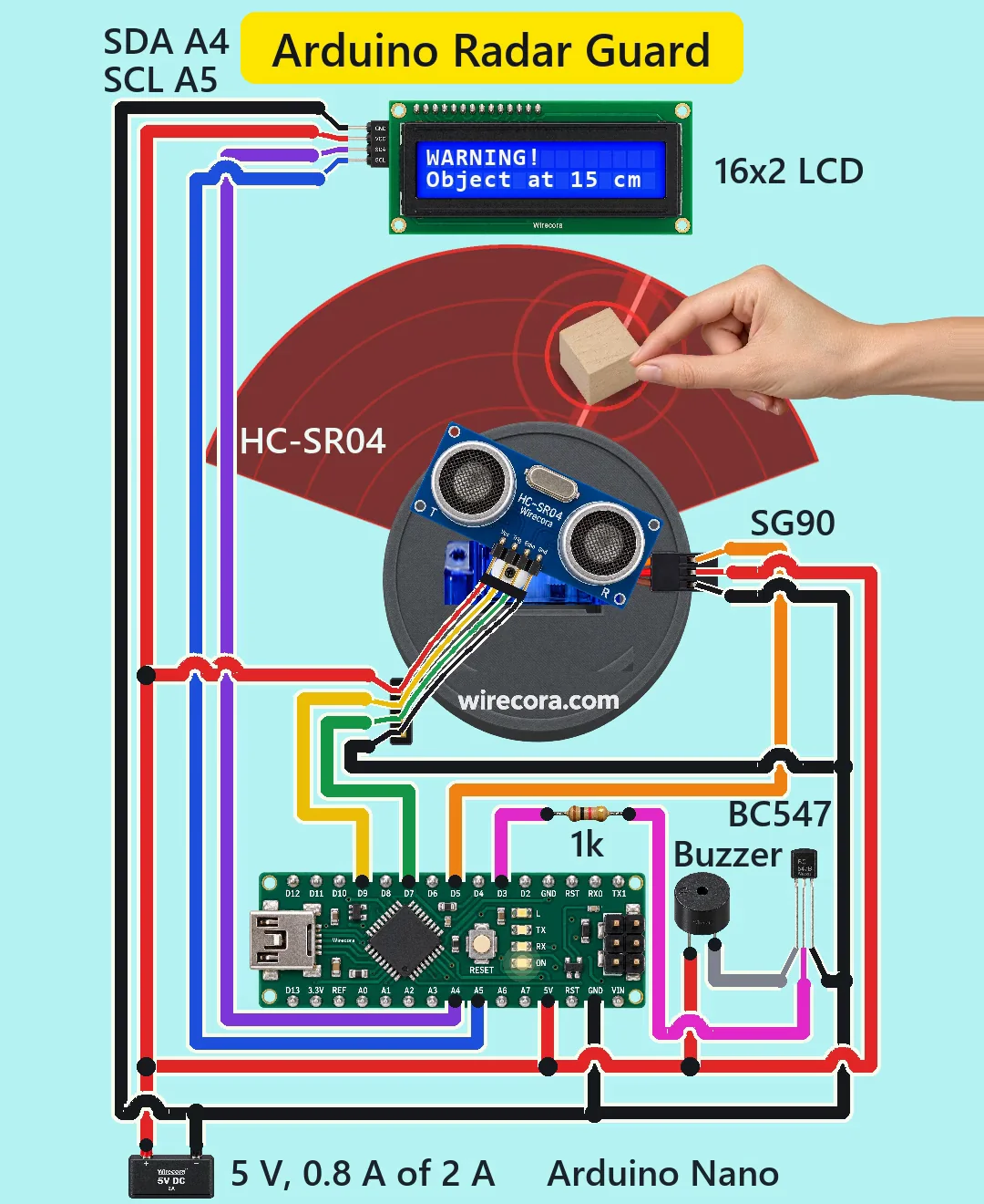
Parts
- Arduino Nano (an Uno works the same: same chip, same pins, same sketch)
- HC-SR04 ultrasonic sensor, 5 V, about 15 mA, pins Vcc, Trig, Echo, Gnd from left to right (2 cm to 4 m, 15 degree beam)
- SG90 micro servo (brown GND, red VCC, orange signal)
- 16x2 LCD with an I2C backpack (PCF8574), pins GND, VCC, SDA, SCL; address 0x27 assumed, some are 0x3F; about 25 mA with the backlight on
- Active 5 V buzzer, 12 mm, with its own oscillator (it beeps by itself when it gets 5 V; about 30 mA, 2.3 kHz)
- BC547 NPN transistor (flat face towards you, legs down: C, B, E from the left)
- 1 k resistor, 1/4 W, for the transistor's base (bands brown, black, red, gold)
- Regulated 5 V 2 A power supply
- A base or stand for the servo, and a flexible four-wire lead from the sensor to the board, long enough to let it turn 140 degrees
- Recommended and not drawn in the Short: a 100 to 470 uF capacitor rated 10 V or more across the servo's red and brown wires, a 10 k resistor from the BC547 base to its emitter, and a 1N4148 diode across the buzzer
How it is wired
- Supply plus (5 V) to the Nano's 5V pin, the HC-SR04 Vcc, the LCD VCC, the servo's red wire and the buzzer's plus (long) leg.
- Supply minus to a Nano GND pin, the HC-SR04 Gnd, the LCD GND, the servo's brown wire and the BC547 emitter (E). One supply, one common ground.
- Nano D9 to HC-SR04 Trig; HC-SR04 Echo to Nano D7.
- Nano D5 to the servo's orange (signal) wire.
- Nano A4 to LCD SDA; Nano A5 to LCD SCL. The backpack has its own pull-up resistors.
- Nano D3 to the 1 k resistor; the other end of the resistor to the BC547 base (B).
- BC547 collector (C) to the buzzer's minus (short) leg.
- Optional: 100 to 470 uF (10 V or more) across the servo's red and brown wires (stripe to brown), 10 k from the BC547 base to its emitter, and a 1N4148 across the buzzer with its band (cathode) on the 5 V side.
How it works
- Every 60 ms the Nano sends a 10 microsecond pulse to Trig. The HC-SR04 sends out a burst of ultrasound and holds Echo high until the echo comes back. The Nano divides that time in microseconds by 58 to get centimetres. It stops listening after 2.4 ms, so anything farther than about 35 cm counts as nothing.
- With nothing near, the servo turns 5 degrees per loop, from 20 to 160 degrees and back: about 1.7 s from one end to the other.
- A reading between 2 and 30 cm locks the radar: the sweep stops, the LCD shows WARNING! and the distance, and the buzzer gives three beeps of about 0.18 s with 0.18 s gaps, once per lock.
- If the object moves and the next ping hears nothing, the sketch looks 5 degrees to the left on the next loop, then 5 degrees to the right on the one after, and keeps the side that hears it. That is how it follows the object. After two empty searches it unlocks, the LCD says Area is Empty and the sweep goes on.
- The buzzer takes about 30 mA, more than the 20 mA an Arduino pin should give, so D3 only drives the BC547's base: (5 - 0.7) / 1 k = 4.3 mA. At its minimum gain of 110 the transistor needs 0.27 mA just to pass 30 mA; 4.3 mA is about 16 times that, enough to switch it fully on (saturated).
- Worst case the whole circuit takes about 0.75 A from the supply (most of it a stalled servo, about 0.65 A), well under 2 A. The servo takes its current straight from the regulated supply, not through the Nano or USB; the recommended capacitor across the servo smooths its current spikes so they do not dip the board's 5 V.
The code: radar_guard.ino
The Arduino code for this circuit is in the Wirecora Discord, in the channel #arduino-code (owner’s choice, 14 October 2026: the code lives where you can ask about it). It is a plain .ino file you can download there.
The sketch the Short was animated from, run step by step in a simulation at its real 60 ms loop; it has not been run on a real board yet. It needs the Servo library (built in) and LiquidCrystal_I2C by Frank de Brabander (Sketch, Include Library, Manage Libraries). If the screen stays blank, change 0x27 to 0x3F or turn the contrast trimmer on the backpack.
What the video simplifies
- The radar fan, its range rings, the trail and the echo rings are drawn to show what the sensor measures. A real HC-SR04 shows nothing, and ultrasound is silent.
- The beam is drawn narrow, so the sweep stops with its centre line on the block. A real HC-SR04 has a 15 degree beam: it notices a block about 15 degrees earlier, at its edge, and stops pointing up to about 15 degrees beside it.
- The sensor is drawn lying face-up so its two round transducers can be seen. In a real build it stands upright on the servo horn and looks forward.
- The parts are drawn much larger than the 40 cm radar picture, and the Nano is drawn wider than the LCD so its pins stay readable.
- Each 5 degree servo step is drawn over 50 ms; a real SG90 makes it in about 10 ms.
- The beeps in the video are softer and lower than a real active buzzer's 2.3 kHz tone, and the servo sound is synthesised.
- A wooden block echoes well. Soft or slanted things (a sweater, a cat's fur) send back much less, so the radar may miss them.
- The plan for the video had two status LEDs and a capacitor on the servo supply; they were left out to keep the picture readable. The capacitor is worth adding in a real build.
- This circuit was checked by simulation and against the datasheets, not built.
Everything runs on 5 V. Feed the 5V pin only from a regulated 5 V supply, never a battery or anything above 5.5 V, and unplug that supply before you plug in USB to upload the sketch.
Build it yourself
The wiring board cannot run an Arduino program yet, so this one cannot be opened on it. Start with the guided first build on the wiring board, where a circuit really works as you wire it, then try the ready-made ones.
Your first circuit, step by stepAll circuits from the Shorts
Stuck, or built it?
Ask about this circuit or show your build in the Wirecora Discord. Questions get an answer every day.