Servo control with a 555 and two buttons
Hold the top button and the servo horn swings one way. Let go and it comes back to its rest position. Hold the lower button and the horn swings the other way, then comes back again when the finger lifts. In the Short the horn swings a full half turn each way; a real MG995 moves about a quarter turn each way with these pulses (see Simplified).
From the Short Servo Motor Control Circuit | NE555 Timer + MG995 (417K views, posted 2026). Opens on YouTube.
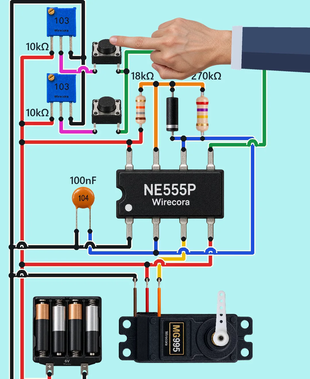
Parts
- NE555P timer, DIP-8
- MG995 servo (positional, 4.8 to 7.2 V) with its orange signal, red and brown wires
- Two 10 k trimmers (printed 103), one for each button
- Two tactile push buttons
- 18 k resistor (RA)
- 270 k resistor (RB)
- 1N4148 diode
- 100 nF ceramic capacitor (104), the timing capacitor
- 4 x AA battery pack, 6 V
How it is wired
- Battery plus (+6 V) to 555 pin 8 (VCC), pin 4 (RESET), the servo's red wire, one end of the 18 k, and the top end of both trimmers.
- Battery minus (GND) to 555 pin 1, the other leg of the 100 nF, the servo's brown wire, and the bottom end of both trimmers.
- The other end of the 18 k to 555 pin 7 (DISCH). The diode's anode is also on pin 7, and one end of the 270 k.
- Diode cathode (band) and the other end of the 270 k to 555 pin 2 (TRIG) and pin 6 (THRES), which are joined. The 100 nF goes from these pins to GND.
- Trimmer 1 wiper through button 1 (top) to 555 pin 5 (CONT). Trimmer 2 wiper through button 2 (lower) to pin 5 too.
- 555 pin 3 (OUT) to the servo's orange signal wire.
How it works
- The 555 runs as a free-running timer. The capacitor fills from +6 V through the 18 k and the diode (the diode lets the charge go round the 270 k, so the fill is quick), and empties slowly through the 270 k into pin 7. The empty time is about 19.4 ms and the whole cycle about 21 ms, so the output pulses about 47 to 48.5 times a second (47 to 48.5 Hz); a standard servo accepts 40 to 60 Hz.
- Pin 5 sets the voltage the capacitor fills to (and it empties to half of that), so it sets how long each pulse stays high. With no button pressed, pin 5 sits at 4 V (two thirds of 6 V, from the 555's own divider) and the pulse is about 1.5 ms, so the horn rests near its middle.
- Holding button 1 puts trimmer 1's wiper on pin 5, about 3.3 V in the Short: the pulse becomes 1.0 ms and the horn swings to one side. Holding button 2 puts about 4.4 V on pin 5: the pulse becomes 2.0 ms and the horn swings to the other side.
- Let the button go and pin 5 returns to 4 V, so the horn comes back to rest. This is a hold-to-move circuit.
- The 555 is fed 6 V because a bipolar 555 drives its output only to about 1.7 V below the supply voltage, so about 4.3 V here; at 6 V the pulse is high enough for the servo. 6 V is inside the MG995 range (4.8 to 7.2 V) and the NE555 range (4.5 to 16 V).
What the video simplifies
- The horn swing is dramatised. The Short maps 1.0, 1.5 and 2.0 ms to 0, 93 and 180 degrees. By its fact sheet a real MG995 (0.5 ms = 0, 1.5 ms = 90, 2.5 ms = 180 degrees) moves only about 90 degrees with these pulses, roughly 45 to 135 degrees, and rests near 90 degrees.
- The pulse widths (1.0, 1.5 and 2.0 ms) come from a simulation of the drawn circuit and are correct for it; the 50 Hz pulse train itself is not drawn.
- The output is about 47 to 48.5 Hz, not exactly 50 Hz (270 k is the resistor used; 250 k would give 50 Hz).
- The trimmer screws do not turn in the Short; their set positions are 45.9 % and 77.7 %.
- Four alkaline AA cells give 6 V but not the MG995's stall current (about 1 A or more). A real build should use NiMH cells or a 5 to 6 V supply that can give 2 A. The horn moves unloaded in the Short.
- Not drawn, but add in a real build: 470 uF across the servo supply and 10 nF from pin 5 to GND.
- The part art is generic: the diode is drawn as a chunky black body, a real 1N4148 is a small glass part with a black band; the buttons show two legs, real ones have four. The signal wire is yellow in the drawing while the servo's own wire is orange.
Everything runs on 6 V from AA cells; the servo can pull over 1 A when the horn is blocked and can get warm, so let it move freely and do not short the battery pack. Check the battery polarity before you connect it: nothing in this circuit protects the 555 or the servo from a reversed pack.
Build it yourself
The wiring board has no 555, no capacitors and no servo yet, so this one cannot be opened on it. Start with the guided first build on the wiring board, where a circuit really works as you wire it, then try the ready-made ones.
Your first circuit, step by stepAll circuits from the Shorts
Stuck, or built it?
Ask about this circuit or show your build in the Wirecora Discord. Questions get an answer every day.