Yard skeleton head that turns to look at you, with two PIR sensors, an Arduino Nano and two servos
A trick-or-treater walks up on one side of the path and the giant skeleton's skull turns to look straight at them, the jaw clacks three times and the eyes glow red. A second kid on the other side gets the same. 2.5 seconds after the last new trigger the head turns back to the front, even if that sensor still sees the kid. It looks to one of two fixed sides, left or right: a PIR sensor only knows that something moved, so it does not follow you step by step.
From the Short Skeleton Head Turns to Look at You (Arduino + 2 PIR sensors) (posted 24 October 2026). Opens on YouTube.
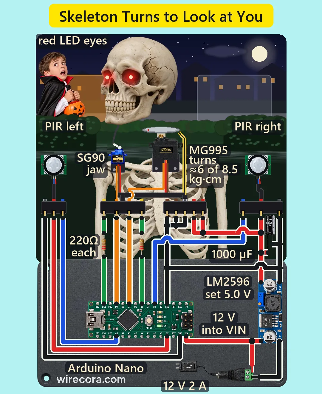
Parts
- Arduino Nano (an Uno works the same: same chip, same pins, same sketch)
- Two HC-SR501 PIR motion sensors (4.5 to 20 V supply, their own 3.3 V regulator, OUT goes to 3.3 V on motion; pins GND, OUT, VCC: go by the labels on your board), each in a short black tube so it sees only one side of the path
- MG995 servo for the neck (4.8 to 7.2 V, about 8.5 kg·cm at 4.8 V; brown GND, red plus, orange signal)
- SG90 micro servo for the jaw (about 1.8 kg·cm; brown GND, red plus, orange signal)
- LM2596 buck converter module (3.5 to 40 V in, output set with its trimmer; about 1.5 A continuous)
- 1000 uF 25 V electrolytic capacitor across the 5 V servo supply
- Two red 5 mm LEDs for the eyes and two 220 ohm resistors, 1/4 W
- DC barrel jack (5.5 x 2.1 mm, centre pin +) and a regulated 12 V 2 A adapter, centre positive
- The prop: a large yard skeleton, a lazy-susan bearing between the neck post and the skull, a bracket for the MG995 under it, a bracket for the SG90 on the collarbone, and a push-pull cable (a stiff wire in a housing) from the SG90 horn to the jaw
- Wires, servo extension leads for the run down the neck, and a box for the electronics
How it is wired
- Adapter into the barrel jack. Jack + (centre pin) to the Nano's VIN pin and to the LM2596 IN+. Jack minus to the LM2596 IN-. Never put 12 V on the Nano's 5V pin.
- Before any servo is plugged in: power the LM2596 and turn its trimmer until a meter reads 5.0 V on OUT+ and OUT-. The modules do not ship set to 5 V, and 12 V would destroy both servos.
- LM2596 OUT+ is the 5 V servo rail, OUT- is GND. The 1000 uF goes across them: long leg on OUT+, stripe leg on GND.
- MG995 red and SG90 red to the 5 V servo rail. MG995 brown and SG90 brown to GND.
- One common ground: LM2596 OUT- also goes to a Nano GND pin. The Nano's two GND pins are joined on the board, so either one works.
- Neck: MG995 orange to Nano D7. Jaw: SG90 orange to Nano D9.
- Left PIR: VCC to the Nano's 5V pin, GND to Nano GND, OUT to Nano A0 (read as a normal digital input).
- Right PIR: VCC to the 5 V servo rail, GND to GND, OUT to Nano D3. If it ever triggers by itself when the servos move, move its VCC to the Nano's 5V pin too.
- Eyes: Nano D11 through a 220 ohm resistor to the left LED's long leg, Nano D5 through the other 220 ohm to the right LED's long leg. Both short legs (cathodes) to GND.
- Set each PIR's jumper to L (single trigger), its time trimmer to the minimum (about 3 s) and its range to about 4 m. Turn each tube about 30 degrees outward so the left one sees only the left of the path and the right one only the right.
- Run the eye lead through the centre of the bearing with a loop of slack, and fix the push-pull cable's housing at both ends (servo bracket and skull) with enough slack for the 120 degree turn.
How it works
- At power-up the sketch sets the neck to the middle (90 degrees) and the jaw shut (20 degrees) before it attaches the servos, so the jaw never swings open past its stop. Then it waits one minute while the PIRs settle.
- A kid walks into the left zone: the left PIR's OUT rises to 3.3 V, which the Nano reads as HIGH (it needs 3.0 V at 5 V). The sketch acts on that rising edge only.
- The neck glides to 150 degrees (60 degrees to the left) in 0.6 s on a smooth start-and-stop curve, a new servo position every 20 ms. In the first 0.3 s the jaw opens to 60 degrees and the eyes fade up to full brightness.
- Then the jaw clacks: shut, open, every 120 ms, three times. On each shut the teeth meet, so the knock you hear is real.
- A kid on the right does the same to 30 degrees. From one side straight to the other (120 degrees) the glide takes 0.9 s.
- While the head is turned, the eyes breathe (a slow brightness wave on D11 and D5). 2.5 s after the last new trigger the head glides back to the front, the jaw shuts and the eyes go dark, even if that sensor is still on.
- The eyes use D11 and D5 because the Servo library takes Timer1, which stops PWM on D9 and D10. D9 is fine as a servo signal. Each eye takes (5 - 1.9) V / 220 ohm = 14 mA, under the pin's 20 mA.
- Torque (an estimate): a 0.7 kg skull turning 60 degrees in 0.6 s on the bearing needs about 6 of the MG995's 8.5 kg·cm. The jaw needs about 0.7 of the SG90's 1.8 kg·cm.
- Currents: about 1.1 A at worst from the 2 A adapter. If a hand holds both the head and the jaw so both servos stall, they would pull about 2.15 A from the 5 V side (an estimate: published MG995 stall currents vary). That is more than the LM2596 board's 1.5 A continuous rating, though still under the chip's own current limit, so the board runs hot, and if the stall goes on its thermal shutdown cuts the 5 V until it cools. The Nano's own regulator takes about 51 mA from 12 V and loses 0.36 W, which it handles.
- Protection: no flyback diode is needed. Nothing switches a bare coil: both servos have their own driver inside, and there is no relay or bare motor. The 1000 uF smooths the current steps when the servos start. There is no reverse-polarity protection: a centre-negative adapter fits the same jack and would damage the LM2596 board and the Nano, so check the centre-positive symbol on the adapter before you plug it in.
The code: skeleton_head.ino
The Arduino code for this circuit is in the Wirecora Discord, in the channel #arduino-code (owner’s choice, 14 October 2026: the code lives where you can ask about it). It is a plain .ino file you can download there.
The sketch the Short was animated from: the same timing and states ran in the video's simulation. It uses the Servo library that comes with the Arduino IDE. It has not been run on a real board. If the head turns away from the kid, swap LOOK_L and LOOK_R. Servos differ in how far they turn for the same command, so if the head turns too far or not far enough, move LOOK_L and LOOK_R closer to or further from 90.
What the video simplifies
- The orange zone bands are drawn so you can see what each sensor watches. Infrared is invisible.
- The electronics are drawn several times larger than the yard, and the 10-ft skeleton smaller than scale, so the pins and labels can be read. A real build hides the board in a box at the skeleton's feet.
- The two PIRs are drawn facing you. In the build each is turned about 30 degrees outward in its tube.
- The PIR settings and timing are assumed: time trimmer at about 3 s, 0.15 s from movement to the OUT signal.
- Assumed: a 0.7 kg skull, a 0.12 kg jaw, the push-pull cable's friction and the servo currents while moving. A bigger 12-ft skull would need a servo of about 25 kg·cm (estimate).
- The drawn turn is smoothed. A real servo chases each 20 ms step at full speed, so it may look a little more stepped.
- Where the MG995's lead leaves the body, its drawn cores change order for a few pixels. Follow the colours: orange signal to D7, red to 5 V, brown to GND.
- The right PIR takes its VCC from the 5 V servo rail. That works (it has its own regulator), but if it false-triggers when the servos move, move it to the Nano's 5V pin.
- The two kids are drawn figures and their reactions are staged. All the sounds are synthesised.
- This circuit was checked by calculation and against the datasheets, not built.
Everything runs on 12 V and 5 V DC from a regulated, certified 12 V adapter; no mains wiring. Set the LM2596 to 5.0 V before the servos are connected. A 10-ft skeleton catches the wind: stake and guy it so it cannot fall onto the path. Keep fingers out of the neck bearing and the jaw while it is powered, and unplug before you work on it. The head only turns and looks; it never moves toward anyone. Put the electronics in a box out of the rain and tape the cables down so nobody trips.
Build it yourself
The wiring board cannot run an Arduino program yet and has no servos or PIR sensors, so this one cannot be opened on it. Start with the guided first build on the wiring board, where a circuit really works as you wire it, then try the ready-made ones.
Your first circuit, step by stepAll circuits from the Shorts
Stuck, or built it?
Ask about this circuit or show your build in the Wirecora Discord. Questions get an answer every day.