Solar power bank with a TP4056 and an 18650 cell
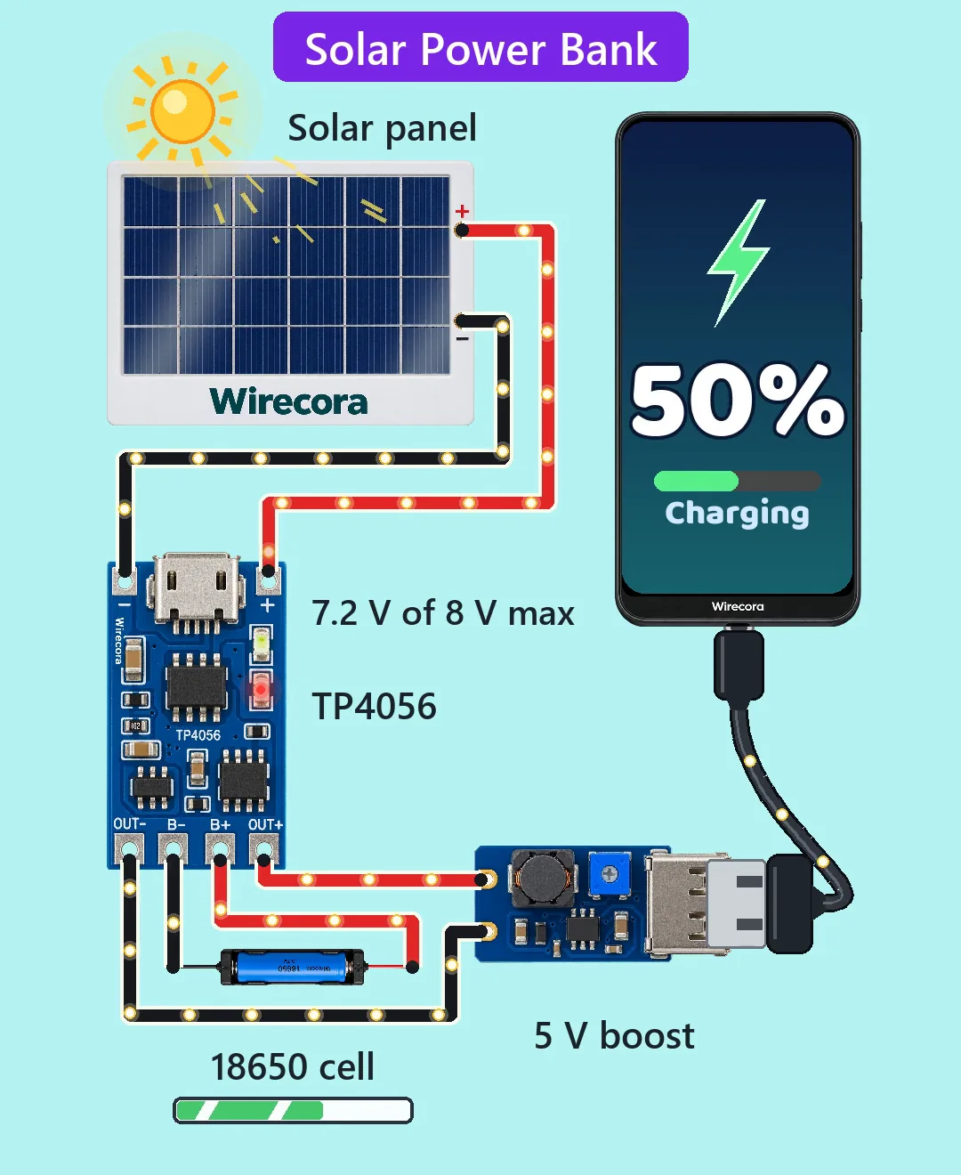
The sun shines on a small solar panel and slowly fills one 18650 lithium cell. Push the USB plug into the phone and the screen lights up: the cell, lifted to 5 V by a boost board, charges the phone. Pull the plug and the panel goes back to filling the cell. It is a top-up: one cell gives about a third of a phone charge.
From the Short Solar Power Bank: Sunlight Charges Your Phone | TP4056 + 18650 (403K views, posted 13 October 2026). Opens on YouTube.
Parts
- Solar panel, about 1 W. The Short draws a 6 V 1 W panel (6 V at 166 mA in full sun, 7.2 V open circuit, 180 mA short circuit). Its open-circuit voltage decides which charger you can use: see the first wiring step.
- TP4056 1 A charger module WITH protection (DW01 and 8205A chips on the board; pads IN- and IN+ at the input end, OUT-, B-, B+, OUT+ along the other end). Its own USB socket is not used.
- 18650 Li-ion cell, 3.7 V (4.2 V full), about 2200 mAh, in a single-cell holder
- MT3608 boost board with a USB-A socket (input 2 to 24 V, output adjustable up to 28 V), set to 5.0 V
- USB cable for your phone
- A multimeter, to check the panel and to set the boost board
- For a panel above 6.5 V open circuit, like the 6 V panel in the Short: a CN3791 solar charger board, 6 V version, in place of the TP4056, and a protected 18650 cell (or a one-cell protection board)
How it is wired
- Check the panel first. Read the open-circuit voltage (Voc) on its label. Then carry it from the shade into full sun and, at once while it is still cool, measure its two wires with nothing connected. If both numbers are 6.5 V or less, the TP4056 is fine. If either is higher, use the CN3791 board: the 6 V panel in the Short gives 7.2 V, and even some panels sold as 5 V give 8 V. A cold panel gives more volts than a warm one, so judge it cool.
- Panel plus to the TP4056's IN+, panel minus to IN-.
- Cell plus to B+, cell minus to B-. Check the cell's direction in the holder before it goes in.
- Set the boost board before any phone: connect its IN+ to OUT+ and its IN- to OUT-, measure the 5 V on the USB socket (the two outer pins) and turn the trimmer until it reads 5.0 V. It is a multi-turn trimmer, so it can take many turns before the voltage moves. A new board can give far more than 5 V.
- Leave the boost board on OUT+ and OUT-, never on B+ and B-: the protection chips sit between B- and OUT-, and wiring the load to B skips them.
- Plug the phone into the boost board's USB socket with a normal cable.
- With a CN3791 board instead: panel to its solar input, cell to its battery pads, boost board to the cell. The board only charges: it does not cut the cell off when it runs low. So use a protected 18650 cell (it is a few millimetres longer, check that it fits the holder) or put a one-cell protection board between the cell and the boost board.
How it works
- The TP4056 charges one lithium cell: first a steady current, then it holds 4.2 V and lets the current fall until it stops. Its 1.2 k PROG resistor allows up to 1 A, but the panel can give only about 0.18 A, so the panel sets the charge current.
- Because the panel cannot give what the chip asks for, the chip pulls the panel's voltage down to just above the cell's, about 4 V with the cell at 3.7 V. So about 0.69 W goes into the cell, not the panel's full 1 W: the TP4056 does not hold the panel at its best working point. The chip itself loses only about 20 mW. About 4 V is also the bottom of the chip's 4 to 8 V working range, so with a low cell the charging may switch off and on and the red light may flicker. The cell still fills, slowly. A CN3791 board holds the panel at its best voltage instead.
- Why the panel voltage matters: the TP4056 takes 4 to 8 V, and 8 V is also its absolute maximum, a level a chip should never be run at. A panel's open-circuit voltage rises about 0.35 % for every degree colder. The 6 V panel's 7.2 V at 25 C becomes about 7.7 V at 0 C and about 8 V at -10 C, and panels vary. When the cell is full the charger stops drawing current, so the panel sits at that open-circuit voltage all day. A panel of 6.5 V or less open circuit stays under about 7.5 V even at -20 C, and it charges just as well, because the chip pulls the input down to about 4 V anyway.
- A 1N5819 diode in the panel lead does not fix this on its own: with the cell full the chip draws only about 55 uA, and at that current the diode drops very little.
- No blocking diode is needed against the night. When the panel's voltage falls to within 30 mV of the cell, the TP4056 goes to sleep and draws under 2 uA from the cell (TP4056 datasheet).
- A 2200 mAh cell takes about 12 hours at 0.18 A, and about 13 to 15 hours of full sun in all with the slow end of the charge: about three sunny days. Three hours of full sun add about a tenth of a phone charge.
- The boost board lifts the cell's 3 to 4.2 V to 5 V. A phone taking 0.5 A at 5 V draws about 0.66 A from a full cell, 0.75 A at 3.7 V and 0.93 A at 3.0 V (about 90 % efficient). That is far below the protection's cut-off of about 3 A or more.
- With the phone plugged in and the sun out, the cell gives the difference: the panel puts in about 0.18 A and the boost takes about 0.75 A, so the cell runs down by about 0.56 A.
- The DW01 and the 8205A switches on the module cut the cell off if it is over-discharged (about 2.4 V), overcharged (about 4.3 V) or shorted.
- Energy: the cell holds about 8.1 Wh, about 7.3 Wh after the boost. A 5000 mAh phone holds about 19 Wh, so one cell is about a third of a charge.
- The red LED on the module stays on while the panel is charging the cell. The green one lights when the cell is full. At night both are off.
What the video simplifies
- The phone's percent climbs about 1200 times faster than real charging, and it starts at 41 % on every plug-in so the loop closes.
- The cell's level bar moves less, and refills faster, than it really would.
- The label "7.2 V of 8 V max" is true at 25 C, but 8 V is the chip's absolute maximum and leaves no margin in the cold. Build it with a panel of 6.5 V or less open circuit, or with a CN3791 board, as in the wiring.
- Not to scale: the boards are drawn larger than the phone, the cell smaller than it is, and the USB-C plug oversized so the hand can hold it.
- The USB cable is drawn as one cable; the two wires inside are not shown.
- The moving dots show only which way the current flows, not how much.
- The boards are drawn next to the panel in the sun. In a build only the panel goes in the sun; the cell and the boards stay in the shade.
- The phone is assumed to take 0.5 A; many phones take more from a USB socket that tells them they may.
- The light on the panel and the sun's rays are decoration, and the sounds are synthesised.
- The circuit in the Short was checked by simulation and against the datasheets, not built. The CN3791 version on this page was checked against its datasheet only.
A lithium cell is safe when it is treated right: never short its two ends, check plus and minus before it goes in the holder, and use the TP4056 module with protection (the one with OUT+ and OUT- pads), or a protected cell with the CN3791 board. Keep the cell and the boards in the shade; only the panel goes in the sun. Charge a Li-ion cell only between 0 C and 45 C (check your cell's sheet; some ask for 10 C or more). Neither board senses the cell's temperature, so do not leave it charging outside on a frosty morning. Check your panel before you connect it (see the wiring). Set the boost board to 5.0 V with a meter before you plug in a phone: it can put out up to 28 V.
Build it yourself
The wiring board has no solar panel, TP4056 module, lithium cell or boost board yet, so this one cannot be opened on it. Start with the guided first build on the wiring board, where a circuit really works as you wire it, then try the ready-made ones.
Your first circuit, step by stepAll circuits from the Shorts
Stuck, or built it?
Ask about this circuit or show your build in the Wirecora Discord. Questions get an answer every day.