Arduino solar tracker with two LDRs and a servo
As the sun crosses the sky, two light sensors tell an Arduino which side is brighter, and a servo turns a small solar panel to face the sun, a few degrees at a time. At sunset it goes back to the middle, ready to swing towards the next sunrise.
From the Short Solar Panel That Follows the Sun | Arduino Solar Tracker (834K views, posted 15 October 2026). Opens on YouTube.
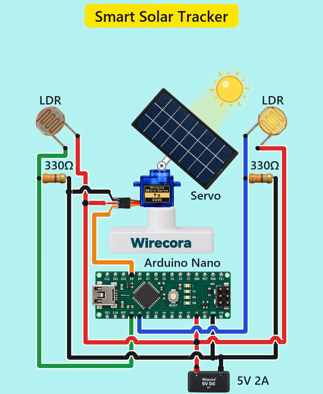
Parts
- Arduino Nano (an Uno works the same)
- SG90 micro servo (brown GND, red VCC in the middle, orange signal; made for about 5 V; 1.8 kg cm; up to about 0.65 A when stalled, a typical figure, as its datasheet gives none). It can turn only a small, light panel balanced on its horn; a heavier panel needs a bigger servo and a bigger supply.
- 2 x GL5528 LDR (light-dependent resistor), two legs, either way round
- 2 x 330 ohm resistor, 1/4 W (bands orange, orange, brown, gold)
- 470 uF 16 V (or higher) electrolytic capacitor (the stripe is the minus side)
- Regulated 5 V 2 A supply
- A small solar panel on the servo horn (the Short uses a 6 V one), a stand, and a piece of card or plastic about 3 cm tall as a shade wall between the two LDRs
How it is wired
- Supply plus (5 V) to the Nano's 5V pin, the servo's red wire, one leg of each LDR and the capacitor's plus (long) leg.
- Supply minus to a Nano GND pin, the servo's brown wire, one end of each 330 ohm and the capacitor's minus (stripe) leg. One common ground.
- The left LDR's other leg to Nano A0 and to one 330 ohm. The right LDR's other leg to Nano A1 and to the other 330 ohm.
- Nano D9 to the servo's orange (signal) wire.
- Put the 470 uF right at the servo plug, across its red and brown wires. Nano VIN stays free.
- In the Short the two LDRs are fixed, tilted 45 degrees to the left and right. For a build that keeps pointing at the sun, fix a small card to the panel's edge with the shade wall standing straight out from the panel. Glue one LDR on each side of the wall, close against it, both facing the same way as the panel: the left one (A0) on the left, the right one (A1) on the right, as seen in the Short. Leave their wires loose enough to follow the panel.
- Fix the servo so it turns the panel from east to west, and balance the panel on the horn.
How it works
- Each LDR and its 330 ohm form a divider: the more light, the lower the LDR's resistance and the higher the voltage on its analog pin. The Nano reads it as a number from 0 to 1023.
- In bright sun (about 20,000 lux assumed) an LDR is about 157 ohm: 3.39 V, a reading of about 693. Turned away (about 400 lux) it is about 1640 ohm: 0.84 V, about 171. At night both read about 8. With the usual 10 k instead of 330 ohm, both would sit near 5 V in sun (4.92 and 4.30 V), and the difference would be about four times smaller. Indoors under a lamp, 10 k works better.
- The Short's sketch keeps the LDRs fixed. It turns 'left reading minus right reading' into a servo angle with a five-point table, waits until the sun is about 6 degrees off, then takes a 13 degree step. That table fits only the light it was made for: in haze or full sun the angle shifts by up to about 10 degrees more.
- With both LDRs on the panel and a wall between them, no table is needed. When the panel faces the sun, both LDRs get the same light. When the sun moves on, the wall shades the LDR on the far side. The sketch on this page turns the servo one degree towards the brighter side every 30 ms, and stops when the two readings are within 30 of each other. That is a closed loop: it needs no table, so haze or full sun changes it little. Two LDRs of the same type can differ a lot, so it may settle a few degrees to one side of the sun; a taller wall makes that smaller.
- When both readings fall under 20 (night), the sketch walks the panel back to the middle (90 degrees). The angle stays between 30 and 150 degrees.
- Power: a stalled SG90 takes about 0.65 A, the Nano about 19 mA and the two dividers about 10 mA each in full sun: 0.69 A of the supply's 2 A. Even a servo that takes 1 A stays inside it. That is too much for a USB port, so the servo runs from the 5 V supply. The 470 uF covers the servo's start-up bursts so the Nano does not reset.
- Each LDR takes at most about 19 mW of its 100 mW, and each 330 ohm about 35 mW (54 mW in 100,000 lux sun) of its 250 mW.
- The servo has its own motor driver inside, so no flyback diode is needed.
The code: solar_tracker.ino
The Arduino code for this circuit is in the Wirecora Discord, in the channel #arduino-code (owner’s choice, 14 October 2026: the code lives where you can ask about it). It is a plain .ino file you can download there.
The closed-loop sketch for the build on this page, with both LDRs on the panel and a shade wall between them. It is not the sketch the Short was animated from (that one, a lookup table for fixed sensors, is in the Short's description). It has not been compiled or run on a real board; its logic was only stepped through in a simple light model on a PC. It uses the built-in Servo library. If the panel turns away from the sun, swap the A0 and A1 wires. Raise BAND if it twitches, lower it if it stops short.
What the video simplifies
- A whole day is squeezed into 6 seconds, but the Arduino and the servo run at real speed, so the panel lags behind the sun; on a real day it keeps up easily. The steps come from the video sketch's 6 degree dead band.
- The sun is drawn close and fades in and out in place. The light beam and the glowing LDR faces are drawn to show which sensor sees more light.
- The light levels are assumed: 20,000 lux for the sun, and the GL5528 at 15 k in 10 lux (its datasheet says 10 to 20 k). Real direct sun can reach about 100,000 lux.
- In the video the LDRs are fixed and the panel follows a table (open loop). This page recommends the LDRs on the panel with a shade wall and gives that sketch; the video's table sketch is in the Short's description.
- The servo is drawn from the side while the panel turns in the picture's plane. On a bench its shaft would point at you. The horn arm is drawn.
- The panel's own output wires are not shown: this circuit runs from the 5 V supply, not from the panel. To charge a battery from the panel you need a charge controller.
- The 470 uF capacitor is not drawn in the video.
- The electronics are drawn larger than the panel and stand, not to scale.
- The viral original drove a motor from a TDA2822 audio amplifier; this one uses an Arduino Nano and a servo.
- The Nano alone uses about 0.1 W, day and night; with a panel this small that can be more than tracking gains. It shows the idea; big trackers use big panels.
- The servo sounds are synthesised.
- This circuit was checked by calculation and against the datasheets, not built. The closed-loop build and its sketch on this page were not part of that check.
Everything runs on 5 V from a regulated supply. Never put a battery or anything above 5.5 V on the 5V pin. Before you plug in USB to upload, unplug the 5 V supply and the servo's plug: the Nano then runs from USB alone, and the servo cannot pull its current from your computer's port. Never look at the sun to check where the panel points. Outdoors, keep the Nano and the supply in a weatherproof box. The GL5528 contains cadmium: EU rules (RoHS) keep such LDRs out of products sold there, so a product would use phototransistors instead, and an old LDR goes to electronics recycling, not the bin.
Build it yourself
The wiring board cannot run an Arduino program yet, so this one cannot be opened on it. Start with the guided first build on the wiring board, where a circuit really works as you wire it, then try the ready-made ones.
Your first circuit, step by stepAll circuits from the Shorts
Stuck, or built it?
Ask about this circuit or show your build in the Wirecora Discord. Questions get an answer every day.