3-way speaker crossover
A test tone sweeps from high to low. Sound waves appear on the tweeter first, then on the midrange, then on the woofer, because each speaker gets only the part of the sound its filter lets through.
From the Short 3-Way Speaker Crossover Circuit (491K views, posted 8 October 2026). Opens on YouTube.
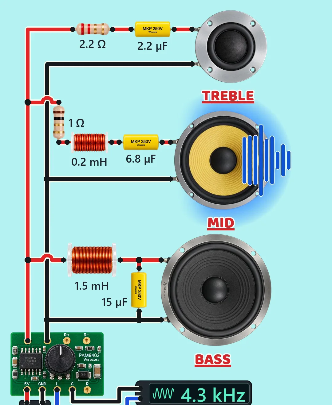
Parts
- PAM8403 class-D amplifier module (its L+ and L- outputs are bridge-tied: both swing, neither is ground)
- 5 V DC supply for the amplifier (a USB port or a battery)
- Tone generator (any audio source) on the amplifier input
- 8 ohm tweeter, midrange and woofer (the numbers on this page treat each one as a plain 8 ohm load)
- Tweeter filter: 2.2 ohm resistor and 2.2 uF film capacitor
- Midrange filter: 1 ohm resistor, 0.2 mH air-core coil and 6.8 uF film capacitor
- Woofer filter: 1.5 mH air-core coil and 15 uF film capacitor
How it is wired
- Supply plus (red) to the amplifier's 5V pad; supply minus (black) to the amplifier's GND pad.
- Tone generator signal to the amplifier input pad L; tone generator ground to the amplifier input pad G.
- Amplifier L+ (the red bus) to the 2.2 ohm resistor, to the 1 ohm resistor and to the 1.5 mH coil.
- Tweeter: 2.2 ohm resistor, then 2.2 uF capacitor, then the tweeter's + lug (upper lug).
- Midrange: 1 ohm resistor, then 0.2 mH coil, then 6.8 uF capacitor, then the midrange's + lug.
- Woofer: 1.5 mH coil, then the woofer's + lug. The 15 uF capacitor goes from that same node (coil to woofer) to the black bus, so it sits across the woofer.
- Amplifier L- (the black bus) to the - lug (lower lug) of all three speakers and to the other end of the 15 uF capacitor. All three speakers are wired the same way round, so they are in phase.
- The amplifier's right-channel pads R, R+ and R- are left unwired (mono).
How it works
- A capacitor in series lets high notes through and blocks low ones; a coil in series does the opposite. The crossover uses this to send each speaker only the sounds it is good at.
- Tweeter: the 2.2 uF capacitor with the 2.2 ohm resistor and the 8 ohm tweeter is a first-order high-pass. Its -3 dB point (where the level has dropped to about 70 % of the voltage, half the power) is at about 7.1 kHz. The 2.2 ohm resistor also turns the tweeter down a little (about -2 dB).
- Midrange: the 1 ohm resistor, 0.2 mH coil and 6.8 uF capacitor in series with the 8 ohm midrange make a band-pass centred at about 4.3 kHz, passing roughly 2 kHz to 9 kHz (the -3 dB points measured from its peak).
- Woofer: the 1.5 mH coil in series and the 15 uF capacitor across the woofer make a second-order low-pass with its -3 dB point at about 1.2 kHz, falling 12 dB per octave above that.
- The hand-overs are at about 9.3 kHz (tweeter to mid, both at -4.1 dB there) and about 1.5 kHz (mid to woofer, both at -6.2 dB there). With these values the mid is still the loudest at 8 kHz; the tweeter takes over only above 9.3 kHz.
What the video simplifies
- The sweep is faster in some bands than others so each speaker gets similar screen time; a real sweep is uniform. The readout shows the true sweep frequency (8 kHz at 1.84 s, 1 kHz at 3.75 s, 200 Hz at 4.77 s).
- The wave bars, the blue glow and the pumping cones are drawn for the video. A speaker shows waves while its level is within 2.5 dB of the loudest one; the bar speed and cone pump are not the tone frequency.
- The speakers are modelled as plain 8 ohm resistors. Real drivers have voice-coil inductance and impedance peaks, and a real midrange would roll off below 9 kHz. With these values the tweeter and mid also overlap strongly from about 7 to 10 kHz.
- The tone generator and the 5 V supply are stand-in boxes; the supply stands for a USB port or a battery.
- The audio is a synthesised sine sweep, shaped so phones can play it.
- The original video drew the 15 uF capacitor across the amplifier output, where it filters nothing; here it sits across the woofer, on the speaker side of the coil, which is the correct place.
Everything here runs on 5 V DC from a USB port or battery; keep the amplifier module and the supply dry. The PAM8403 output is bridge-tied: the black speaker bus is the amplifier's L- output, not ground. Never connect L+ or L- to ground, to the supply minus, or to the tone generator's ground; the speakers and filters must float between L+ and L- only.
Build it yourself
The wiring board has no capacitors, coils or speakers yet, so this one cannot be opened on it. Start with the guided first build on the wiring board, where a circuit really works as you wire it, then try the ready-made ones.
Your first circuit, step by stepAll circuits from the Shorts
Stuck, or built it?
Ask about this circuit or show your build in the Wirecora Discord. Questions get an answer every day.