Start/stop latch with one 5 V relay
Press the green START button once and let go: the relay clicks in and the motor keeps spinning its propeller. Press the red STOP button: the relay drops out and the propeller coasts to a stop. Let go of STOP and nothing starts again until you press START. Machine motor starters use the same start/stop latch; this one runs on a safe 5 V.
From the Short Press START once: this relay keeps the motor running until STOP (893K views, posted 16 October 2026). Opens on YouTube.
Parts
- 5 V relay SRD-05VDC-SL-C, the bare relay with five pins: coil about 70 ohm (71 mA at 5 V, pulls in at 3.75 V or less), changeover contact COM, NO and NC (the datasheet gives 7 A at 28 V DC, 3 A for a motor). Not a relay module: a board with IN, VCC and GND pins needs other wiring.
- START: momentary push button, normally open (green), rated 1 A or more
- STOP: momentary push button, normally closed (red), rated 1 A or more. With two normally open buttons the circuit never starts.
- 130-size DC motor, the 4.5 to 9 V kind (6 V, about 70 mA with no load, 0.5 A stalled), with a light plastic propeller
- 2 x 1N4007 diode (the band is the cathode): one across the relay coil, one across the motor
- 1N5819 Schottky diode (the band is the cathode), in series with the motor
- Regulated 5 V 2 A DC supply
How it is wired
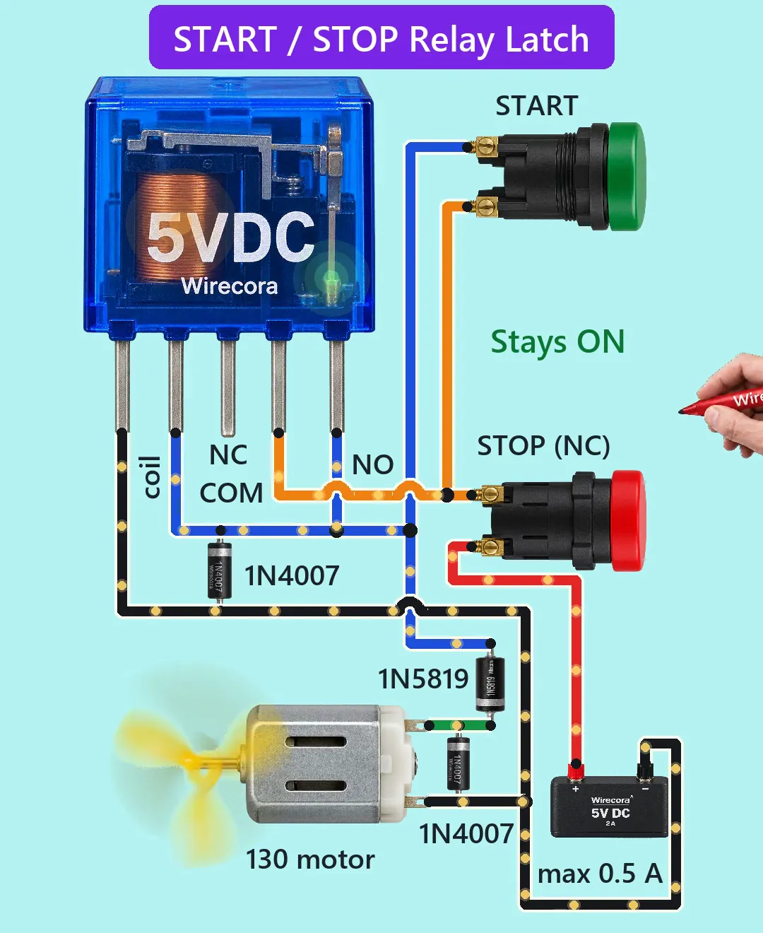
- Before you solder, find the relay pins. On a real SRD-05VDC-SL-C one end has three pins: COM in the middle with a coil pin on each side. The other end has NO and NC. Check with a meter: the two coil pins read about 70 ohm to each other, NC reads 0 ohm to COM, and NO reads open to COM until the coil gets 5 V. The Short draws the five pins in a row (coil, coil, NC, COM, NO), so wire by the names, not by the picture.
- Supply plus (+5 V) to one terminal of STOP.
- STOP's other terminal to one terminal of START and to the relay's COM pin.
- START's other terminal to the relay's NO pin, to one coil pin and to the plain (anode) end of the 1N5819. This joint stays live while the motor runs.
- The 1N5819's band (cathode) end to the motor's plus terminal.
- Supply minus to the relay's other coil pin and to the motor's other terminal. One common ground.
- One 1N4007 across the coil: band on the coil pin that goes to NO, plain end on the coil pin that goes to minus.
- The other 1N4007 across the motor: band on the motor's plus terminal (the 1N5819 side), plain end on minus.
- The relay's NC pin stays free.
How it works
- STOP is closed until you press it, so +5 V always reaches COM and one side of START. Press START and 5 V reaches the coil: it takes 71 mA and pulls the relay in about 5 ms later in simulation (10 ms at most on the datasheet). Its contact joins COM to NO.
- COM to NO is a second path from +5 V to the coil, beside START. When you let go of START the coil is still fed through its own contact, so the relay holds itself in and the motor keeps running. This is called a self-holding or seal-in contact.
- STOP is the only way in from +5 V. Press it and the coil and the motor lose power, so the relay lets go about 5 to 8 ms later in simulation (the diode across the coil slows it a little) and its contact opens. Letting go of STOP changes nothing now: START and the relay contact are both open.
- After a power cut it is the same: the relay has dropped out, and when the power comes back START and the relay contact are both open, so the motor never restarts by itself. Real motor starters are built this way on purpose.
- Why the 1N5819: a motor that is still spinning is a generator. Without this diode the coasting motor would feed the coil after STOP. In simulation the relay then let go 0.06 to 0.5 s late, and with a light propeller on a heavy rotor it was still held when STOP was let go, so the latch closed again and the motor ran on. The Schottky diode lets current go only towards the motor and costs about 0.3 V, so the motor gets about 4.7 V.
- The two 1N4007s are flyback diodes. When the coil or the motor is switched off, its current wants to keep flowing and would make a high voltage spike. The diode gives it a path round the coil or motor, so the buttons and the relay contact do not spark. Both are wired backwards to the supply, so they carry nothing while it runs.
- Currents: coil 71 mA; motor about 0.1 A running with a light propeller and about 0.39 A for the first moment of spin-up; so at most 0.46 A of the supply's 2 A, and about 0.17 A while it runs. The relay contact carries at most 0.46 A, far below the 3 A its datasheet allows for a motor.
- For the few milliseconds before the relay contact closes, START carries the coil and the motor's start current (about 0.46 A), and STOP carries everything while the motor runs. A 6 mm tactile button is rated only 50 mA, so use panel buttons rated 1 A or more.
What the video simplifies
- The viral originals are 230/400 V contactor circuits. This is the same latch at 5 V with one relay; it is not a mains wiring guide.
- The relay is drawn with its five pins in a row and a clear case. A real SRD-05VDC-SL-C has three pins at one end (coil, COM, coil) and NO and NC at the other: wire by the pin names, checked with a meter.
- The relay's moving contact is not animated: a glow on the coil and the contact shows when it is pulled in. The moving dots and the words Stays ON are there to show the current path.
- The propeller is drawn face on and slowed down: about 4.5 turns a second drawn, about 100 for real. The spin-up and coast-down times are chosen.
- START is held down for about 0.6 s; 10 ms would be enough.
- The running current (about 0.1 A) assumes a light propeller and the 4.5 to 9 V version of the 130 motor.
- The parts are drawn large and not to one scale, and the hand is drawn smaller than the parts.
- The clicks, the relay clack and the motor sound are synthesised.
- This circuit was checked by calculation, simulation and the datasheets, not built. The contact rating and the real pin layout on this page come from the relay's datasheet.
Everything runs on 5 V DC from a regulated supply. Do not use this page to wire a mains motor, even though the relay's case may say 250 V AC: a mains start/stop needs a rated contactor, motor overload protection, an emergency stop and, in most countries, an electrician. Keep fingers away from the spinning propeller and use a soft plastic one.
Build it yourself
The wiring board has a 5 V relay module, a push button, a DC motor and both diodes, but no normally closed STOP button and no bare relay coil, so this latch cannot be opened on it yet. Start with the guided first build on the wiring board, where a circuit really works as you wire it, then try the ready-made ones.
Your first circuit, step by stepAll circuits from the Shorts
Stuck, or built it?
Ask about this circuit or show your build in the Wirecora Discord. Questions get an answer every day.