Step-pad porch reaper with a 555 timer and a worm gear motor
Step on the STEP HERE mat and the hooded reaper by the door lunges at you twice with glowing red eyes, then leans back and waits for the next visitor. A 555 timer and a gear motor do it all: there is no code and no microcontroller.
From the Short This Porch Reaper Lunges When Trick-or-Treaters Step on the Mat (posted 24 October 2026). Opens on YouTube.
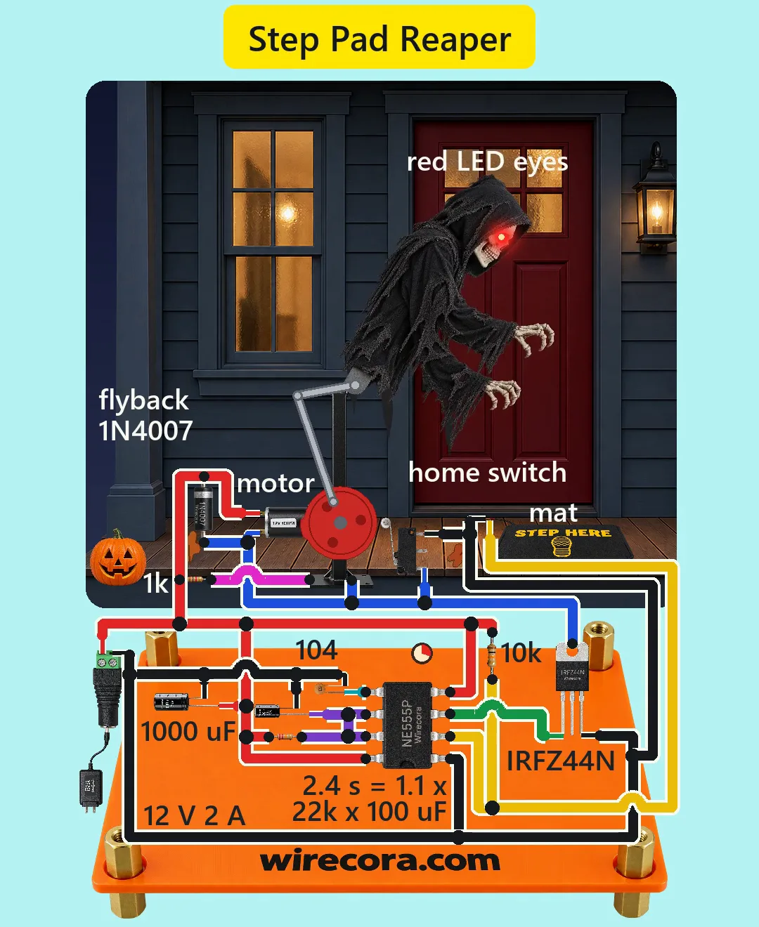
Parts
- NE555 timer, DIP-8 (pin 1 GND, 2 TRIG, 3 OUT, 4 RESET, 5 CTRL, 6 THRES, 7 DISCH, 8 VCC; 4.5 to 16 V)
- IRFZ44N N-channel MOSFET, TO-220 (G, D, S from the left with the print facing you; the metal tab is the drain)
- 1N4007 diode across the motor (flyback)
- Resistors, 1/4 W: 10k (pulls the trigger high), 22k (sets the time), 1k (for the eyes)
- 100 uF 25 V electrolytic (sets the time), 1000 uF 25 V electrolytic (across the supply), 100 nF ceramic marked 104 (on pin 5)
- Two red 5 mm LEDs for the eyes
- JGY-370 12 V 40 rpm worm gear motor (no load 60 mA or less; rated 2 kg·cm at 0.6 A; stall 7.5 kg·cm at 1.7 A; the worm gear holds its position when unpowered)
- Roller lever microswitch, Omron SS-5GL2 type, 5 A resistive at 30 V DC (pins C, NO, NC; only C and NC are used: go by the marks on your switch)
- A STEP HERE pressure mat: a two-wire, normally-open switch that closes while someone stands on it (no polarity: either wire can go to pin 2)
- DC barrel jack (5.5 x 2.1 mm, centre pin +) and a regulated 12 V 2 A adapter, centre positive
- The prop: a light hooded torso (foam skull, thin aluminium tube spine, gauze cloak) on a hip pivot, a stand, and a crank-rocker linkage: crank 90 mm on the motor shaft, rod 440 mm, lever 230 mm on the hip pivot, 550 mm between the motor shaft and the hip pivot
How it is wired
- Jack + (centre pin) is the +12 V rail, jack minus is GND. The 1000 uF goes across the two right at the jack: long leg on +12 V, stripe leg on GND.
- NE555 pin 8 (VCC) and pin 4 (RESET) to +12 V. Pin 1 to GND.
- Pin 2 (TRIG) to one mat wire and through the 10k to +12 V. The mat's other wire to GND. On a real porch, with a long mat lead, add a 100 nF capacitor from pin 2 to GND against noise.
- Pins 6 and 7 joined. The 22k from them to +12 V, the 100 uF from them to GND (stripe on GND).
- Pin 5 through the 104 (100 nF) to GND.
- Pin 3 (OUT) to the IRFZ44N gate. Source to GND. Drain to the motor's minus terminal. The Short wires the drain at the metal tab, which is the same as the middle lead; use either one.
- Motor plus terminal to +12 V. The 1N4007 across the motor: band (cathode) on the +12 V terminal, the other end on the drain side. Fit it right on the motor's terminals, short leads, as in the Short.
- Home switch: C to the drain (the motor minus wire), NC to GND, NO left free. Use the terminals marked C and NC on your own switch. Mount it so the cam lobe on the crank disc presses its roller only when the reaper is in its rest pose.
- Eyes: +12 V through the 1k to the first LED's long leg, its short leg to the second LED's long leg, the second LED's short leg to the drain. In the Short the 1k sits at the motor's +12 V lead, and the two eye wires run up inside the stand tube and the cloak. The eyes light whenever the motor runs.
- Linkage: crank on the motor shaft, rod from the crank pin to the lever, lever fixed to the torso at the hip pivot. If the slow stroke turns out to be the lunge, swap the two motor wires.
How it works
- At rest the mat is open, the 10k holds pin 2 at 12 V, pin 3 is LOW, the MOSFET is off and the cam holds the home switch open: nothing moves and the supply gives only the 555's few milliamps.
- A foot on the mat pulls pin 2 to 0 V, below the 555's trigger level of 4 V (one third of 12 V). Pin 3 goes HIGH, about 10.5 V, well above the IRFZ44N's 4 V maximum threshold, so it turns fully on and the motor and the eyes get 12 V. The mat carries only 1.2 mA.
- Pin 3 stays HIGH for T = 1.1 x 22k x 100 uF = 2.4 s, even after the foot leaves the mat. At 40 rpm the crank turns about 576 degrees in that time: two full lunges. Any time from 1.6 to 2.9 s still gives two lunges, so part tolerances do not matter.
- The crank-rocker linkage turns the motor's steady rotation into a rocking swing of the torso of about 50 degrees, from 20 degrees back to 30 degrees forward, with no dead point anywhere in the turn.
- Soon after the cam leaves the switch at the start, its NC contact closes and joins the drain to GND alongside the MOSFET. So when the timer ends mid-swing, the motor keeps running through the switch until the cam comes round and opens it at the rest pose. The reaper always parks in the same place, and the self-locking worm gear holds it there.
- When the motor stops, the 1N4007 catches the coil's voltage kick (the drain peaks about 12.8 V instead of spiking), which protects the MOSFET and the switch.
- Currents: the motor about 0.4 A running and 1.7 A if it stalls, inside the 2 A adapter; the eyes 8 mA; the MOSFET loses 3 mW running; the switch carries 0.4 A, under a tenth of its 5 A DC rating; the capacitors see at most 12 V of their 25 V.
What the video simplifies
- The electronics are drawn several times larger than the porch, and the motor and the home switch about three times the stand's scale, so the pins and labels can be read. The NE555 is drawn turned on its side so its wires stay short; its pins are the same.
- The cloak is cut short so the crank and the lever show.
- The switch lever is drawn still; the real lever moves as the cam lobe arrives.
- The skull is seen from the side, so only one eye glow shows. The second LED is on the far side.
- The motor speed is the 40 rpm no-load figure; a real one runs 10 to 20 % slower and still makes two lunges. The 40 ms spin-up and the 15 degree coast to rest are assumed.
- The moving torso is assumed light: 0.16 kg (foam skull, gauze cloak, thin tube) with its centre 0.35 m above the hip, which needs 1.23 kg·cm of the motor's rated 2. Above about 0.26 kg the top of the lunge needs more than the rated torque (0.3 kg needs about 2.3 kg·cm, still far from the 7.5 kg·cm stall); a much heavier torso needs a stronger motor.
- A foot left on the mat past 2.4 s keeps it lunging, and a 555 can fire once when the power is plugged in (it then parks).
- The store prop this is remade from also screams. This one has no speaker, so only the motor is heard; a DFPlayer Mini and a speaker on pin 3 would be the next step.
- The frame crops the shoe, and all the sounds are synthesised.
- This circuit was checked by calculation, an ngspice simulation and the datasheets, not built.
Everything runs on 12 V DC from a regulated, certified 12 V adapter; no mains wiring. The crank, rod and lever can pinch fingers: cover the mechanism and unplug before you reach into it. Set the reaper back from the steps so its lunge never reaches a visitor, keep the mat flat and taped down so nobody trips, and remember that a scare on a staircase can make a child step back and fall. Keep the gauze cloak away from real candles: use an LED light in the pumpkin. Put the electronics in a box out of the rain. For very young trick-or-treaters, unplug it.
Build it yourself
The wiring board has no 555, no gear motor and no linkage yet, so this one cannot be opened on it. Start with the guided first build on the wiring board, where a circuit really works as you wire it, then try the ready-made ones.
Your first circuit, step by stepAll circuits from the Shorts
Stuck, or built it?
Ask about this circuit or show your build in the Wirecora Discord. Questions get an answer every day.