Take-one candy bowl with an Arduino, a load cell and an MG995 servo
The bowl weighs its own candy. Take one bar and nothing happens. Grab a fistful and the light bar under the bowl flashes red, the screen says ONLY ONE! and a skeleton arm throws up a sign. Put the extras back: the count on the screen drops with every bar, and at one bar the light turns green, the screen says THANK YOU and the arm folds down. A second later the bowl counts again from its new weight.
From the Short Grab Too Much Halloween Candy and This Bowl Calls You Out (posted 25 October 2026). Opens on YouTube.
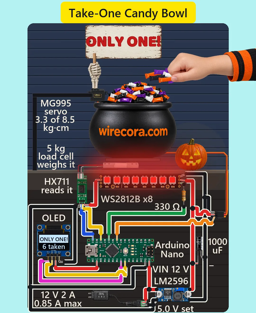
Parts
- Arduino Nano (an Uno works the same: same chip, same pins, same sketch)
- HX711 load cell amplifier, the green module: header GND, DT, SCK, VCC; pads E+, E-, A-, A+, B-, B+ (2.6 to 5.5 V; the chip takes under 1.5 mA and the load cell about 4 mA more; 10 readings a second because the module ties its RATE pin low; 24 bit)
- 5 kg straight bar load cell, about 1.0 mV per volt and about 1000 ohm, four leads red, black, green and white, with a base block, a spacer and a platform for the bowl
- MG995 metal-gear servo (4.8 to 7.2 V; 8.5 kg·cm and 0.2 s per 60 degrees at 4.8 V; brown GND, red VCC in the middle, orange signal; about 1.5 A when stalled, a typical seller figure)
- WS2812B stick with 8 LEDs (5 V; about 18 mA per colour per LED at full; at the input end the pads are GND, DIN, 5VDC, GND counted from the mounting-hole edge; the output end has the same order with DOUT, and its 5V and GND pads sit on the same copper tracks as the input end's)
- 330 ohm resistor for the light bar's data line
- LM2596 buck converter module (input 3.5 to 40 V, 1.5 A continuous, 2 A for short peaks; IN and OUT grounds are joined on the board), its trimmer set to 5.0 V
- 1000 uF 25 V electrolytic capacitor (the stripe is the minus side)
- 0.96 inch SSD1306 I2C OLED, 128 x 64, pins GND, VCC, SCL, SDA from left to right (some boards swap GND and VCC: follow the print), 3.3 to 5 V and up to 20 mA, address 0x3C (a few use 0x3D)
- DC barrel jack to screw terminal adapter (5.5 x 2.1 mm, centre pin +) and a regulated 12 V 2 A adapter, centre positive
- A plastic cauldron about 30 cm across, a light skeleton forearm and hand (about 40 g), a foam-board sign about 25 x 12 cm with a stick, a post and bracket that hold the servo behind the bowl, and a rubber stop on the post for the arm to rest on
How it is wired
- First set the converter. Connect only the 12 V supply to the LM2596 IN+ and IN-, put a meter on OUT+ and OUT-, and turn the trimmer until it reads 5.0 V. A new module can come set to any voltage. Plug in the servo and the light bar only after this.
- Adapter into the DC jack. Jack + (the centre pin) to the LM2596 IN+, and from that wire to the Nano's VIN pin (made for 7 to 12 V). Never put 12 V on the Nano's 5V pin.
- Jack minus to the LM2596 IN-. On the module IN- and OUT- are the same copper, so this is the one ground every part shares.
- LM2596 OUT+ to the light bar's 5VDC pad at its input end (the third pad from the mounting-hole edge) and to the servo's red wire. LM2596 OUT- to the light bar's GND pad at the input end (the fourth pad) and to the servo's brown wire. In the Short these are the red and the black rail up the right side. The servo and LED current runs on them to the converter and never flows through the Nano.
- 1000 uF across the 5 V rail: plus (long) leg on OUT+, stripe leg on OUT-. Put it right at the servo plug if you can.
- Servo orange (signal) to Nano D6.
- Nano D8 through the 330 ohm resistor to the light bar's DIN pad. Put the resistor at the light bar's end of the wire. Use the input end of the stick (DIN), not the DOUT end. The first GND pad at the input end stays free.
- HX711 VCC to the light bar's 5V pad at the far (output) end. That pad is on the stick's own 5 V track, so the HX711 runs from the same 5.0 V as the LEDs; with its load cell it takes about 6 mA. The output end's DOUT and GND pads stay free.
- A second ground wire from the jack's minus: the HX711 GND, the OLED GND and the Nano GND in the row with VIN all join it. The Nano's other GND pin and its 5V pin stay free.
- HX711 DT to Nano D12, HX711 SCK to Nano D10.
- OLED VCC to the Nano's 3.3V pin (the screen takes up to 20 mA; the pin gives up to 50 mA on an official Nano). OLED SDA to Nano A4, OLED SCL to Nano A5. If the screen stays dark or freezes on a clone Nano, whose 3.3V pin is weaker, move OLED VCC to the Nano 5V pin: the module takes 3.3 to 5 V.
- In the Short the OLED is mounted upside down, pins at the bottom, so the sketch calls oled.setRotation(2) and the text reads upright. If you mount it pins on top, delete that line.
- Load cell to the HX711: red to E+, black to E-, green to A+, white to A-. B- and B+ stay free. Some cells use other colours, so check your cell's sheet. If the weight reads negative, swap green and white.
- Bolt the cell's fixed end (where the leads leave) to the base through a block, and the platform to the other end through a spacer, so the bar is free to bend. If the bar has an arrow, it points down. The platform and the bowl must touch nothing else, not the servo post and not the step.
- Fix the servo on its bracket on the post behind the bowl with the skeleton arm on its horn, not on the platform. The arm rests on a rubber stop on the post, not on the bowl: anything resting on the bowl is weighed. Upload the sketch, then change DOWN until the arm rests on its stop and UP until the sign stands straight up.
How it works
- The load cell is a metal bar with four strain gauges in a bridge. The HX711 feeds it about 4.3 V and amplifies the tiny difference on A+ and A-. Cauldron, platform and about 60 bars weigh about 1.6 kg: well under the cell's 5 kg, and a signal of about 1.4 mV, far inside the HX711's range (about +-17 mV). One 16 g bar changes the signal by about 14 microvolts, hundreds of times the HX711's noise.
- The HX711 gives the Nano 10 readings a second. CAL turns the counts into grams: find it once with a known weight. At power-up the sketch waits 0.5 s and zeroes the full bowl, so it counts what leaves, not what is in it.
- Why 25 g: a fun-size bar weighs about 14 to 20 g (0.5 to 0.7 oz). One bar is always under 25 g and two are always 28 g or more, so the 25 g limit tells one from two. The number on the screen is grams divided by 16, so with mixed candy it can be off by one; the alarm is not.
- A reading counts only when it is steady: within 2 g of the one before. So a quick press on the candy, or a bar landing on the pile, never trips anything. Pressing makes the bowl heavier, and the sketch only counts what is gone.
- READY: the light bar breathes green. When a steady reading shows more than 25 g gone, the sketch goes to ALARM: the OLED shows ONLY ONE! and the count, the light bar goes red and the servo swings the arm up to 90 degrees, with the sign straight up. After the move the light bar flashes red, 200 ms on and 200 ms off (2.5 flashes a second, under the 3 a second limit for flashing light).
- When a steady reading shows 25 g or less gone, the sketch goes to THANKS: green, THANK YOU, and the arm folds down one degree every 10 ms, which takes about a second. The first steady reading after that makes the new weight the zero, and the bowl is READY again. If nobody puts the candy back, it gives up 10 s after the alarm, folds the arm and starts over. After 3 s of steady readings in READY it also takes any change that did not trip the alarm (one bar taken, a refill, drift) as the new zero.
- The servo is attached only while it moves. The NeoPixel library turns interrupts off while it sends colours to the LEDs, which would stretch the servo's pulses and make it twitch. With the servo detached the LEDs can flash freely. At rest the arm lies on its rubber stop, and upright the arm and sign stand balanced over the shaft, so a detached servo holds both with no current and no buzz. The loop waits while the arm moves; the HX711 simply waits too.
- Throwing the arm up needs about 3.3 kg·cm (1.2 to hold the sign out flat plus about 2.1 to speed it up) of the MG995's 8.5 at 4.8 V. The arm, hand and sign weights are assumed: about 80 g in all.
- The light bar's data line: a Nano HIGH is about 5 V and a WS2812B at 5 V needs at least 3.5 V, so no level shifter is needed. The 330 ohm resistor protects the first LED's input and limits a wiring fault to about 15 mA, under the Nano pin's 20 mA.
- Power, worst case: a stalled MG995 (about 1.5 A) plus the 8 LEDs in red (about 0.15 A) take 1.65 A at 5 V, inside the LM2596's 2 A peak. From the 12 V side that is 5 V x 1.65 A / (12 V x 0.85) = 0.81 A, plus about 45 mA for the Nano, the OLED and the HX711: about 0.85 A of the adapter's 2 A at the very peak. While the arm moves it is about 0.37 A, at rest about 0.1 A. The Nano's regulator feeds only the Nano and, through its 3.3V pin, the OLED: (12 - 5) V x about 40 mA = 0.28 W, which is fine. The sketch never sets the LEDs to full white.
- The OLED's I2C lines idle at about 3.5 to 3.9 V: the screen's pull-ups go to 3.3 V and the Nano's weak internal ones to 5 V. The Nano reads that as HIGH in practice, but it sits right at the datasheet minimum of 3.5 V, which is why a dark or frozen screen on a clone Nano is fixed by moving OLED VCC to 5V.
- On USB alone the Nano and the screen come on, but the scale, the servo and the LEDs stay off: they run from the LM2596, which needs the 12 V adapter.
- The 1000 uF on the 5 V rail covers the servo's start-up pulses and the LEDs' switching, so the Nano does not reset. No flyback diode is needed: the servo has its own driver and nothing switches a bare coil. There is no reverse-polarity diode, so use only a centre-positive adapter (check the symbol on its label).
- Why weight and not a camera: the bowl knows by grams how many bars left, so no person and no camera has to judge. A patient kid can still take one, wait three seconds and take another. It stops grabbing, not patience.
The code: take_one_candy_bowl.ino
The Arduino code for this circuit is in the Wirecora Discord, in the channel #arduino-code (owner’s choice, 14 October 2026: the code lives where you can ask about it). It is a plain .ino file you can download there.
The sketch the Short was animated from, with two small changes for a real board: a 0.5 s wait before the tare (the HX711 needs 400 ms to settle after power-up), and each servo write placed before attach, so the first pulse goes where the arm already is. The same logic ran in the video's simulation on the weights in the video; this sketch has not been compiled or run on a real board. It needs the HX711 Arduino Library (by Bogdan Necula), Servo, Adafruit NeoPixel, and Adafruit SSD1306 with Adafruit GFX. Find CAL once with a known weight, as the HX711 library's README explains. The setRotation(2) line is for a screen mounted upside down, as in the Short. Switch on with the full bowl in place.
What the video simplifies
- The electronics and the light bar are drawn about five to six times larger than the porch, and the servo about 1.5 times, so the pins and labels can be read. The child's hand is drawn large too.
- Every bar in the animation weighs 16 g. Real fun-size bars weigh 14 to 20 g, which is why the alarm limit is 25 g.
- The five bars drop back one at a time, so the count can be followed. A real hand lets go of them in a clump.
- The pile is drawn the same at each loop, although one bar leaves each time.
- The label 0.85 A max is the worst-case peak (a stalled servo plus the red LEDs), not normal use. While the arm moves it is about 0.37 A.
- The 1000 uF is drawn on the rails between the servo plug and the LM2596, for lack of room. In a build, put it at the plug. Electrically both work here.
- The OLED text is drawn in a smooth font. The real SSD1306 with setTextSize(2) shows blocky letters with the same words.
- The servo's speed (about 270 degrees a second with the sign) is a model figure; the sheet gives 300 degrees a second with no load at 4.8 V.
- The hand hovers about 4 cm over the pile while it drops the bars back; the model counts no push from the hand then.
- The load cell picture is mirrored left to right. The lead colours and the HX711 pad order are unchanged.
- The Nano's pin names are not printed at each wire in the video; they are all on this page.
- Assumed: the weights of the cauldron (450 g), the platform (200 g), the arm and the sign, the servo's 0.5 A running current and its 1.5 A stall current (a typical seller figure, not from the MG995 sheet).
- All the sounds are synthesised.
- This circuit was checked by simulation and against the datasheets, not built.
The electronics run on 12 V and 5 V from a regulated, certified 12 V adapter. Never put 12 V on the Nano's 5V pin, and set the LM2596 to 5.0 V before you plug in the servo and the light bar. The arm swings up fast: mount it behind the bowl so its whole path is clear of the reach and of faces, use a light foam-board sign and a hollow prop arm with no sharp points, and keep fingers out of the servo, the horn and the bracket. Do not hold the arm while it moves; a stalled servo draws about 1.5 A and gets hot. The light bar flashes at 2.5 times a second, under the 3 a second limit for flashing light; do not make it faster. Use only wrapped candy. On a porch, tape the cables down so nobody trips on the steps, and keep the electronics in a box out of rain and out of reach of little hands.
Build it yourself
The wiring board cannot run an Arduino program yet and has no load cell or LED strip, so this one cannot be opened on it. Start with the guided first build on the wiring board, where a circuit really works as you wire it, then try the ready-made ones.
Your first circuit, step by stepAll circuits from the Shorts
Stuck, or built it?
Ask about this circuit or show your build in the Wirecora Discord. Questions get an answer every day.