Treadmill safety key stop with an Arduino Nano, a reed switch and a 5 V relay
A runner jogs on a small model treadmill with a red magnet key clipped from their top to the console. They stumble back, the cord pulls the key off and the belt coasts to a stop within about a third of a second. Clip the key back on and nothing moves until you press START; then the belt runs again. Many home treadmills use the same idea: a magnet in the key and a switch behind the dock. This one is a 5 V model, not a real treadmill.
From the Short Why Your Treadmill Has a Magnet Clip: It Stops the Belt (posted 28 October 2026). Opens on YouTube.
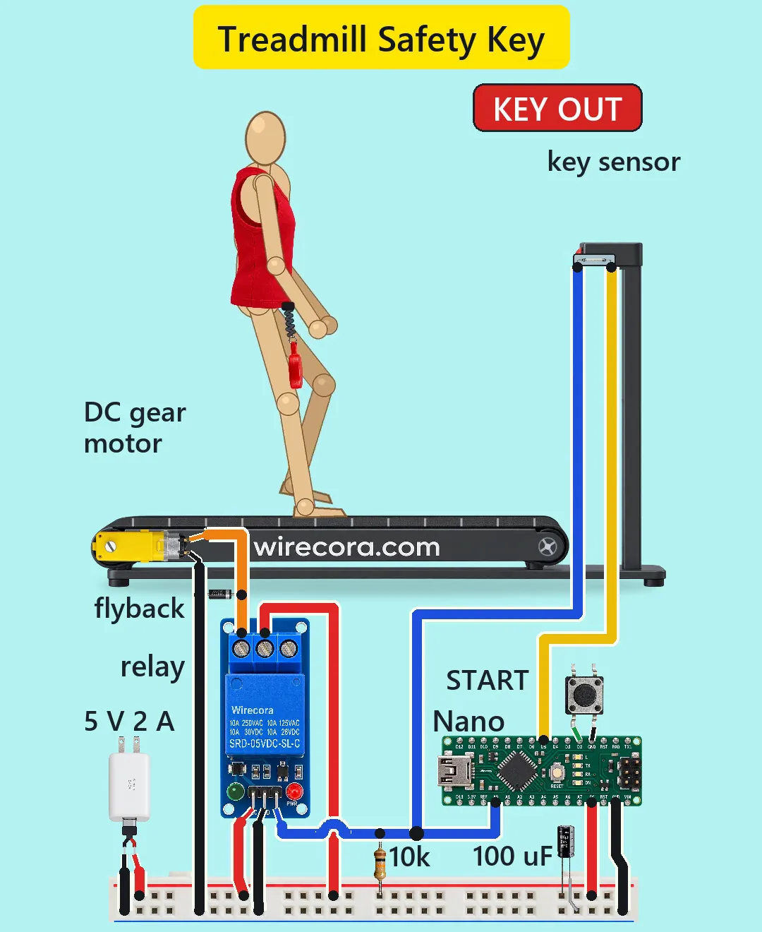
Parts
- Arduino Nano, 5 V (an Uno works the same with the same pin numbers)
- 1-channel 5 V relay module with an SRD-05VDC-SL-C relay (header VCC, GND, IN; screw terminals NO, COM, NC; contacts 10 A at 30 V DC). It is active LOW: the relay pulls in and its green LED lights while IN is LOW. Its coil diode is already on the board
- Glass reed switch, normally open (closes near a magnet; 0.5 A switching, 1.2 A carry)
- A magnet in the key, on a coiled cord with a clip (a small neodymium disc glued into a plastic key works)
- Push button for START (a 6 mm tactile button is fine: it only carries the pin's pull-up current)
- TT gear motor, 3 to 6 V, 1:48 gearbox (not polarised; about 0.15 A free, about 1.3 A for a moment at start or stall at 5 V)
- 1N4007 diode across the motor (flyback)
- 10k resistor, 1/4 W (pull-up on the relay's IN)
- 100 uF 25 V electrolytic capacitor across the 5 V rail
- Regulated 5 V 2 A USB adapter with its cable cut (red = +5 V, black = ground). It must be regulated: the Nano's 5V pin has no regulator in front of it
- Half breadboard and jumper wires
- The model: a small treadmill (about 34 cm long) whose rear roller (about 33 mm across) sits on the motor's output shaft
How it is wired
- Adapter red to the breadboard's + rail, adapter black to the - rail. One supply and one ground for everything.
- Nano 5V pin to the + rail and a Nano GND pin to the - rail. Leave VIN unused and never put more than 5 V on the 5V pin.
- Relay module VCC to the + rail, GND to the - rail.
- Nano D5 to one lead of the reed switch. The reed's other lead to the relay module's IN, to Nano A0, and through the 10k to the + rail. The reed sits right behind the key's dock, so the seated magnet holds it closed.
- START button between Nano D2 and GND. Use two legs that are joined only while the button is pressed (check with a meter); the other two legs stay free.
- Relay COM to the + rail. Relay NO to one motor terminal; the other motor terminal to the - rail. NC stays free.
- 1N4007 across the motor: band (cathode) on the terminal joined to NO, plain end on the terminal joined to ground.
- 100 uF across the rails, long lead on +, stripe on -.
- If the belt runs the wrong way, swap the two motor wires.
How it works
- To run, the Nano holds D5 LOW. That LOW reaches the relay's IN only through the closed reed switch, so the relay pulls in and COM to NO feeds the motor with 5 V.
- Pull the key: the magnet moves away, the reed opens (in our model past about 21 mm), and the 10k pulls IN up to 5 V. The relay lets go within a few milliseconds by itself, in hardware, even if the sketch had frozen. The motor loses power and the belt coasts down.
- The 1N4007 catches the motor's voltage kick when the relay contact opens, so the contact barely sparks.
- The sketch sees A0 go HIGH and sets D5 HIGH too, so the belt stays stopped. Not restarting when the key goes back is done in code: if the sketch had hung while running, putting the key back would start the belt again. That is one reason real treadmills use a tested controller.
- While stopped, D5 is HIGH, so both reed leads sit at 5 V and A0 reads HIGH whether the key is in or out. So every 50 ms the sketch pulls D5 LOW for just 10 microseconds and reads A0. The relay needs up to 10 ms to move and its coil current reaches well under 1 mA in 10 microseconds, so it never clicks. The Nano's L LED lights while the key is out.
- Press START with the key back: after a 20 ms debounce the sketch drives D5 LOW, checks that A0 reads LOW (key in), and the relay pulls in. With the key still out it does nothing.
- Why the reed is not simply in the motor wire: a reed switch handles 0.5 A, and the motor takes about 1.3 A for a moment at start. So the relay's 10 A contact switches the motor and the reed carries only the relay board's input current: up to about 20 mA (one maker's sheet asks for 15 to 20 mA; many boards draw less), plus 0.5 mA through the 10k. D5 sinks that current, which is about Arduino's 20 mA per-pin working figure and well under the chip's 40 mA absolute limit.
- Currents: about 0.35 A from the adapter while running and about 1.4 A for a moment at start, under its 2 A. The relay contact carries at most about 1.3 A of its 10 A.
- The 100 uF smooths the motor's brush noise on the shared 5 V rail. It does not supply the start current; the adapter does.
- Belt speed: the motor turns about 167 rpm at 5 V, so the 33 mm roller moves the belt about 290 mm a second.
The code: treadmill_safety_key.ino
The Arduino code for this circuit is in the Wirecora Discord, in the channel #arduino-code (owner’s choice, 14 October 2026: the code lives where you can ask about it). It is a plain .ino file you can download there.
The sketch the Short was animated from, modelled frame by frame against the video; it has not been run on a real board yet. No libraries needed. The one added line in the START wait loop stops the belt if the key is pulled while START is still held. If the belt runs the wrong way, swap the two motor wires.
What the video simplifies
- The treadmill is a 34 cm desk model with a wooden mannequin, and the stumble is staged. The motor turns the rear roller directly; real treadmills drive the front roller by a belt from a big motor under the hood.
- The electronics are drawn about 3.5 times the model's scale, so the relay looks bigger than the motor, and the key is drawn about 1.5 times its size. The magnet inside the key is not shown; the label magnet key names it.
- The KEY OUT, PRESS START and RUN pills show the sketch's state. A real build only lights the Nano's L LED while the key is out.
- The 10 microsecond check pulse is far too short to see, so nothing on screen shows it.
- The relay module's pin names are hidden under the wire ends in the Short: the header is VCC, GND, IN from the left, the terminals NO, COM, NC.
- The TT motor is drawn turned around so its shaft sits on the roller, and the Nano is drawn loose above a power-rail strip rather than plugged into a breadboard.
- The start current, belt friction, spin-down and spin-up times, the magnet's reach (the reed closes under about 17 mm and opens past 21 mm) and the relay board's input current are assumed or typical values.
- The sketch on this page adds one line the video's sketch lacks: if the key is pulled while START is still held down, it also stops there. It cannot happen in the Short, where START is let go at once.
- All the sounds are added.
- This circuit was checked against the datasheets and a frame-by-frame model of the sketch, not built.
Everything runs on a regulated 5 V USB adapter; no mains wiring. This is a demo of the idea, not a certified safety stop: never wire it into a real treadmill or any machine a person stands on, which run on mains power and need a tested controller. To upload the sketch, unplug the adapter and leave the key out, so the relay cannot start the motor from the computer's USB port. Keep fingers away from the rollers and the belt while it is powered.
Build it yourself
The wiring board cannot run an Arduino program yet, so this one cannot be opened on it. Start with the guided first build on the wiring board, where a circuit really works as you wire it, then try the ready-made ones.
Your first circuit, step by stepAll circuits from the Shorts
Stuck, or built it?
Ask about this circuit or show your build in the Wirecora Discord. Questions get an answer every day.