Joystick LED ring colour sweep
Turn the joystick in a circle and the whole ring runs through the colour wheel. The angle of the stick sets the colour of all 16 LEDs, dimly. The LED at the stick angle is brighter, with one more trailing behind it, so the sweep still reads. Turn the stick the other way and the sweep and the colours reverse with it.
- 6 parts
- 6 wiring steps
- Arduino code
- 5 V supply
Quick answer
The short version. Every pin is in the full wiring below.What you need
- Arduino Nano, powered through its 5V pin
- KY-023 style joystick module
- 16 LED WS2812B ring
- 470 ohm resistor
- 1000 uF 25 V electrolytic capacitor across the ring's power
- 5 V 2 A regulated power supply
How to wire it
- Supply plus (red) to the Nano 5V pin, the joystick +5V, the ring 5V pad and the capacitor's plus lead.
- Supply minus (black) to the Nano GND, the joystick GND, the ring GND pad and the capacitor's stripe.
- Joystick VRx to Nano A7.
- Joystick VRy to Nano A6.
- Nano D6 to the 470 ohm resistor, and the other end of the resistor to the ring's DIN pad.
- Leave the joystick SW pin, the Nano VIN pin and the ring's DOUT pad unconnected.
Before you power it: All 5 V. Power the circuit through the Nano's 5V pin, upload the sketch first with the supply off, and never plug in USB at the same time. Do not set every LED to full white: the ring would then draw about 1 A. Keep the brightness values low as in the sketch.
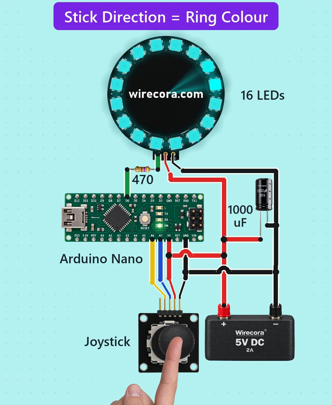
Parts list
- Arduino Nano, powered through its 5V pin (no USB plugged in at the same time)
- KY-023 style joystick module (header SW, VRy, VRx, +5V, GND as drawn with the pins up; check the labels on your own module)
- 16 LED WS2812B ring (Adafruit NeoPixel Ring 16 class; pads DIN, 5V, GND)
- 470 ohm resistor, 1/4 W, in the ring's data line, at the ring end
- 1000 uF 25 V electrolytic capacitor across the ring's power (the stripe side is minus)
- 5 V 2 A regulated power supply
Wiring, step by step
- Supply plus (red) to the Nano 5V pin, the joystick +5V, the ring 5V pad and the capacitor's plus lead.
- Supply minus (black) to the Nano GND, the joystick GND, the ring GND pad and the capacitor's stripe.
- Joystick VRx to Nano A7. A7 and A6 sit right beside 5V on the Nano header and can only read analog values, which is all this needs.
- Joystick VRy to Nano A6.
- Nano D6 to the 470 ohm resistor, and the other end of the resistor to the ring's DIN pad. Put the resistor close to the ring.
- Leave the joystick SW pin, the Nano VIN pin and the ring's DOUT pad unconnected.
How it works
- The joystick is two 10k potentiometers between 5V and GND, one per direction. Each wiper sends a voltage between 0 and 5 V to A7 or A6, about 512 counts when the stick is in the middle.
- Every 20 ms the sketch reads both axes and takes each reading away from 512, so the middle is 0. If either axis is at least 121 counts from the middle (outside the dead band), atan2 turns the two numbers into an angle, and the angle picks one of the 16 LEDs as the head.
- The sketch works out which way the head moved last. The head number (0 to 15) becomes the colour: hue = head x 4096 out of 65536, so one full turn of the stick is the whole rainbow. All 16 LEDs light dimly in that colour (value 28 out of 255), the head at 80 and the LED behind it at 54.
- One data wire from D6 drives the whole ring. The 470 ohm resistor sits at the ring end, and the 1000 uF capacitor across the ring's power is Adafruit's advice to protect the LEDs when the power comes on.
- With every LED lit in colour the ring takes about 80 mA at worst (two colour channels at 20 mA each, scaled by the brightness value) and the whole circuit about 0.12 A, far under the 2 A supply. The sketch keeps brightness low; with all 16 LEDs white at full the ring would draw about 1 A.
The code: joystick_led_radar.ino
The Arduino code for this circuit is in the Wirecora Discord, in the channel #arduino-code (owner’s choice, 14 October 2026: the code lives where you can ask about it). It is a plain .ino file you can download there.
The sketch printed in the Short's description (the colour version). It uses the Adafruit NeoPixel library (Sketch, Include Library, Manage Libraries). The animation was produced by running this sketch's own logic step by step, but it has not been run on a real board; the axis direction and LED 0 differ between modules, so change SIGN and OFFSET if the sweep is off or runs backwards.
What the video simplifies
- The coloured cone from the ring's centre toward the lit LEDs is drawn for effect; real WS2812B LEDs do not light the middle of the board.
- Brightness is drawn following the square root of the coded value so it shows on a phone.
- The electronics are drawn much larger than the hand, and the sound is added.
- The ring picture is AI-generated and rebuilt to 16 LEDs. Its DOUT pad is left open and not drawn.
- Which way the joystick axes run and where LED 0 sits differ between modules and rings. The Short assumes LED 0 at 9 o'clock with the chain running counter-clockwise; if the colour or the sweep is off or runs backwards, swap or invert the axes and change SIGN and OFFSET in the sketch.
- The current figures (ring about 80 mA at worst, about 0.12 A in total) come from general datasheet numbers, not from a measurement.
- This is our own version of a viral idea, checked from datasheets and the sketch, not built.
You found this by searching. Here's the whole path.
- Read how it works
- See it work
- Build it
- Show it
Thirty seconds of video shows the circuit doing its job.
All 5 V. Power the circuit through the Nano's 5V pin, upload the sketch first with the supply off, and never plug in USB at the same time. Do not set every LED to full white: the ring would then draw about 1 A. Keep the brightness values low as in the sketch.
Built it, or stuck halfway? Post a photo in the Wirecora Discord. Questions get an answer every day.
What to build next
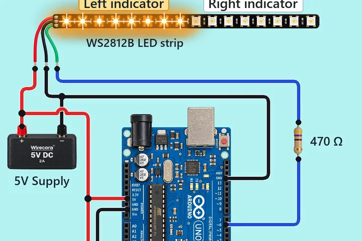 Same Arduino + LED stripSmart bike indicatorsLean the bike to the left and the left half of the LED strip sweeps amber from the middle outwards.
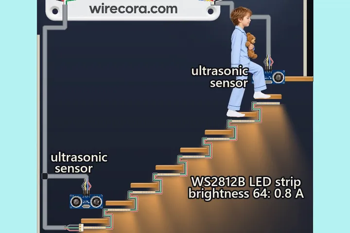 Next step: adds an ultrasonic sensorStair lights that follow you, with an Arduino and two HC-SR04 sensorsWalk up to the bottom step and the stair lights up one step after another, ahead of you, all the way to the top.
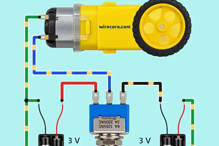 Something new: a motorReverse a motor with one plain toggle switchThe wheel spins one way, the lever flips, and the same wheel spins back the other way.