Adjustable voltage regulator · TO-220
LM317 Pinout
Printed face toward you, metal tab at the back, legs pointing down, left to right: 1 adjust, 2 output, 3 input (ADJ-OUT-IN). The metal tab is joined to the output.
An adjustable regulator: two resistors set any output from 1.25 V to 37 V, up to 1.5 A.
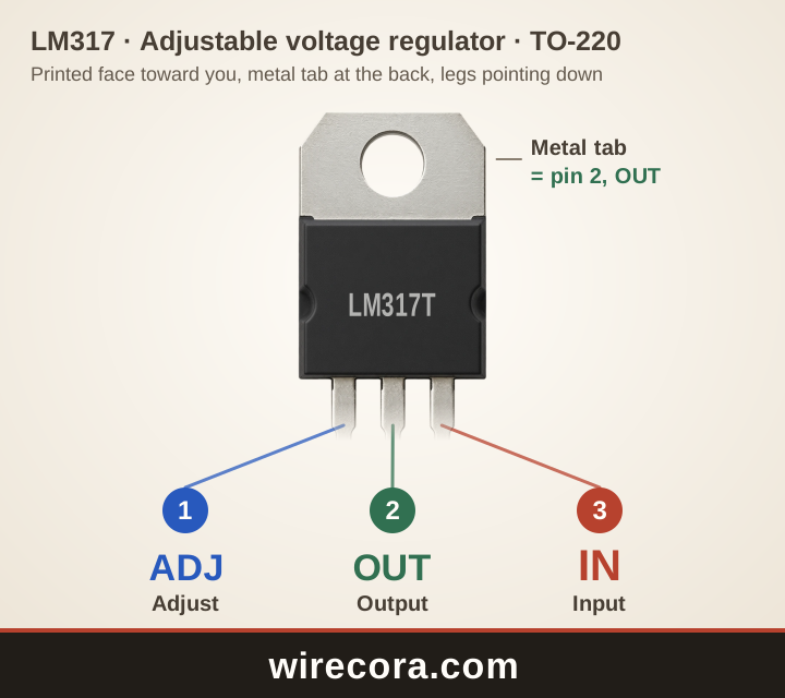
- Pin 1: Adjust (ADJ)Sets the output voltage: the middle of the two-resistor divider connects here.
- Pin 2: Output (OUT)The set voltage comes out here, always 1.25 V above ADJ. Also joined to the metal tab.
- Pin 3: Input (IN)The unsteady supply comes in here: at least 3 V above the output you set.
Metal tab: joined to pin 2, the output, inside the part.
Check your part before wiring. Read the maker and the full part number printed on it, open that maker's datasheet, or test the legs with a multimeter's diode setting.
PNG 1440 × 1280 pixels, SVG to any size. Both keep the wirecora.com mark along the bottom.
Pinout table
Which leg of the LM317 is which?
| Pin | Name | What it does |
|---|---|---|
| 1 | Adjust ADJ | Sets the output voltage: the middle of the two-resistor divider connects here. |
| 2 | Output OUT | The set voltage comes out here, always 1.25 V above ADJ. Also joined to the metal tab. |
| 3 | Input IN | The unsteady supply comes in here: at least 3 V above the output you set. |
| Tab | Metal tab OUT | Joined to pin 2, the output, so it carries the same voltage. Keep it away from other metal unless you mean it to touch. |
Key ratings
How much can the LM317 take?
From the Texas Instruments datasheet: LM317 3-Pin Adjustable Regulator (SLVS044Z). Stay well inside these limits: they are the most the part takes, not what it should run at.
Open the Texas Instruments datasheet (PDF)Pin order by maker
Is every LM317 wired ADJ-OUT-IN?
The TI datasheet numbers the TO-220 legs 1 adjust, 2 output, 3 input (ADJ-OUT-IN) with the printed face toward you, and joins the tab to the output.
That is not the 7805's order: an LM317 dropped into a 7805's place gets its input on the wrong leg. The negative LM337 uses yet another order, so check its own datasheet too.
A first circuit
Set 5 V or 3.3 V from a 9 V or 12 V supply
- Supply plus to IN, with 0.1 µF from IN to 0 V.
- R1 = 240 Ω from OUT to ADJ.
- R2 from ADJ to 0 V: 750 Ω gives about 5.2 V, 390 Ω gives about 3.3 V.
- A 1 µF capacitor from OUT to 0 V. Take the set voltage from OUT.
Put a 5 kΩ potentiometer in place of R2 and you have a bench supply from 1.25 V up to about 3 V below the input. Like the 7805, it turns the extra voltage into heat.
LM317 questions
What is the LM317 pinout?
With the printed face toward you and the legs down, from left to right: adjust, output, input (ADJ-OUT-IN). The metal tab is the output.
How do I set the LM317 output voltage?
Fit 240 Ω from OUT to ADJ (R1) and a second resistor from ADJ to 0 V (R2). The output is 1.25 V × (1 + R2 / R1): 750 Ω gives about 5.2 V, 390 Ω about 3.3 V. The datasheet's full formula adds the small current out of ADJ times R2 (IADJ × R2, about 50 to 100 µA times R2), which makes the result a little higher; the two values above already include it.
What input voltage does an LM317 need?
At least 3 V more than the output you set, and never more than 40 V above it. For a 5 V output, give it 8 V or more.
Can I use an LM317 in place of a 7805?
Yes, with R1 and R2 added to set 5 V, but not in the same holes without rewiring: the 7805 is IN-GND-OUT and the LM317 is ADJ-OUT-IN.
Can I use this pinout picture?
Yes. Download it as PNG or SVG and use it in notes, lessons or posts. The wirecora.com mark along the bottom stays in the picture.
Pin order and ratings from the Texas Instruments datasheet named above. Last reviewed .