N-channel MOSFET · TO-220
IRF540N Pinout
Printed face toward you, metal tab at the back, legs pointing down, left to right: 1 gate, 2 drain, 3 source (G-D-S). The metal tab is joined to the drain.
A 100 V N-channel power MOSFET for motors and lamps on 12 V to 48 V supplies; it needs about 10 V on its gate.
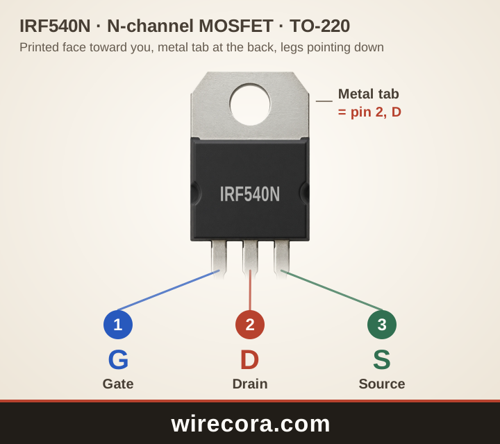
- Pin 1: Gate (G)The control pin. The voltage between gate and source turns it on; almost no current flows in.
- Pin 2: Drain (D)Goes to the load. Also joined to the metal tab.
- Pin 3: Source (S)Goes to 0 V (ground) when the MOSFET switches the low side of a load.
Metal tab: joined to pin 2, the drain, inside the part.
Check your part before wiring. Read the maker and the full part number printed on it, open that maker's datasheet, or test the legs with a multimeter's diode setting.
PNG 1440 × 1280 pixels, SVG to any size. Both keep the wirecora.com mark along the bottom.
Pinout table
Which leg of the IRF540N is which?
| Pin | Name | What it does |
|---|---|---|
| 1 | Gate G | The control pin. The voltage between gate and source turns it on; almost no current flows in. |
| 2 | Drain D | Goes to the load. Also joined to the metal tab. |
| 3 | Source S | Goes to 0 V (ground) when the MOSFET switches the low side of a load. |
| Tab | Metal tab D | Joined to pin 2, the drain, so it carries the same voltage. Keep it away from other metal unless you mean it to touch. |
Key ratings
How much can the IRF540N take?
From the Infineon (International Rectifier) datasheet: IRF540NPbF HEXFET Power MOSFET (Rev. 2.1). Stay well inside these limits: they are the most the part takes, not what it should run at.
Open the Infineon (International Rectifier) datasheet (PDF)Pin order by maker
Is every IRF540N wired G-D-S?
The Infineon datasheet numbers the legs 1 gate, 2 drain, 3 source (G-D-S) with the printed face toward you, and the tab is the drain. Vishay's IRF540, without the N, has the same G-D-S order.
The ratings are not the same, though: the IRF540N is 33 A, 44 mΩ and 130 W, the older IRF540 28 A, 77 mΩ and 150 W. Parts marked IRF540N from other makers normally keep G-D-S, but check before wiring.
A first circuit
Switch a 12 V motor with a tiny switch
- Motor from +12 V to the drain. Source to 0 V.
- A diode (1N4007) across the motor, its striped end to +12 V, to catch the motor's voltage kick.
- A 10 kΩ resistor from the gate to the source keeps the MOSFET off.
- A 100 Ω resistor from the gate to a small switch, and the switch's other side to +12 V. Switch on: the gate gets 12 V and the motor runs.
The switch carries almost no current, so a tiny slide switch controls amps. From a 5 V Arduino pin the IRF540N only half turns on: use an IRLZ44N, or a driver that gives the gate 10 V.
IRF540N questions
What is the IRF540N pinout?
With the printed face toward you and the legs pointing down, from left to right: gate, drain, source (G-D-S). The metal tab is the drain.
Can I drive an IRF540N from an Arduino?
Not well. Its resistance is only promised at 10 V on the gate, and its threshold is 2 to 4 V, so from a 5 V pin it may only half turn on and get hot. Use a logic-level IRLZ44N, or a gate driver.
What is the difference between the IRF540 and the IRF540N?
The legs are the same (G-D-S, tab = drain), the ratings are not: the IRF540N is 33 A, 44 mΩ and 130 W, Vishay's IRF540 28 A, 77 mΩ and 150 W.
IRF540N or IRFZ44N?
Both are G-D-S and both need about 10 V on the gate. The IRFZ44N has lower resistance (17.5 mΩ) but takes only 55 V; the IRF540N takes 100 V, which leaves room on 24 V to 48 V supplies.
How much current can an IRF540N take without a heatsink?
It can shed only about 2 W in free air, so plan on a few amps with a full 10 V on the gate. The 33 A in the datasheet needs the case held at 25 °C.
Can I use this pinout picture?
Yes. Download it as PNG or SVG and use it in notes, lessons or posts. The wirecora.com mark along the bottom stays in the picture.
Pin order and ratings from the Infineon (International Rectifier) datasheet named above. Last reviewed .