NPN power transistor · TO-220
TIP31C Pinout
Printed face toward you, metal tab at the back, legs pointing down, left to right: 1 base, 2 collector, 3 emitter (B-C-E). The metal tab is joined to the collector.
A 3 A, 100 V NPN power transistor in TO-220, for lamps, small motors and simple amplifiers.
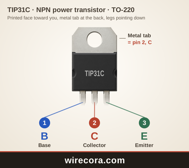
- Pin 1: Base (B)The control pin. A small current into it, always through a resistor, switches the transistor on.
- Pin 2: Collector (C)Goes to the load (LED, relay, buzzer). Current flows in here and out of the emitter.
- Pin 3: Emitter (E)Goes to 0 V (ground) when the transistor is used as a switch.
Metal tab: joined to pin 2, the collector, inside the part.
Check your part before wiring. Read the maker and the full part number printed on it, open that maker's datasheet, or test the legs with a multimeter's diode setting.
PNG 1440 × 1280 pixels, SVG to any size. Both keep the wirecora.com mark along the bottom.
Pinout table
Which leg of the TIP31C is which?
| Pin | Name | What it does |
|---|---|---|
| 1 | Base B | The control pin. A small current into it, always through a resistor, switches the transistor on. |
| 2 | Collector C | Goes to the load (LED, relay, buzzer). Current flows in here and out of the emitter. |
| 3 | Emitter E | Goes to 0 V (ground) when the transistor is used as a switch. |
| Tab | Metal tab C | Joined to pin 2, the collector, so it carries the same voltage. Keep it away from other metal unless you mean it to touch. |
Key ratings
How much can the TIP31C take?
From the onsemi datasheet: TIP31G, TIP31AG, TIP31BG, TIP31CG (NPN), TIP32 series (PNP) Complementary Silicon Plastic Power Transistors (TIP31A/D, Rev. 17). Stay well inside these limits: they are the most the part takes, not what it should run at.
Open the onsemi datasheet (PDF)Pin order by maker
Is every TIP31C wired B-C-E?
The onsemi datasheet numbers the legs 1 base, 2 collector, 3 emitter (B-C-E) with the printed face toward you, and joins the metal tab to the collector.
Because the tab is the collector, two TIP31Cs bolted to one bare heatsink have their collectors joined. Use an insulating pad and washer for each, or give each its own heatsink. Parts from other makers usually follow the same order, but check their datasheet.
A first circuit
Switch a small 12 V load from a 5 V pin
- Load (a short LED strip or a small 12 V fan, up to about 0.3 A) from +12 V to the collector. Emitter to 0 V, shared with the Arduino's 0 V.
- For a fan or motor, a diode (1N4007) across it, striped end to +12 V.
- A 220 Ω resistor from the 5 V pin to the base: about 18 mA, near the most a pin should give.
- Pin high: the load runs. Pin low: it stops.
With a gain of only 25 or so, a pin cannot drive the TIP31C much past 0.3 A. For more, put a BC547 in front of it, or use a TIP120 or IRFZ44N.
TIP31C questions
What is the TIP31C pinout?
With the printed face toward you and the legs down, from left to right: base, collector, emitter (B-C-E). The metal tab is the collector too.
Is the metal tab of a TIP31C live?
Yes. It is joined to the collector, so it carries the load voltage. Do not let it touch other metal unless you mean it to.
What is the difference between TIP31, TIP31A, TIP31B and TIP31C?
Only the voltage rating: 40, 60, 80 and 100 V. The current (3 A) and the leg order are the same.
What is the PNP version of the TIP31C?
The TIP32C, in the same datasheet, with the same B-C-E leg order.
Can I use this pinout picture?
Yes. Download it as PNG or SVG and use it in notes, lessons or posts. The wirecora.com mark along the bottom stays in the picture.
Pin order and ratings from the onsemi datasheet named above. Last reviewed .