−5 V negative voltage regulator · TO-220
7905 Pinout
Printed face toward you, metal tab at the back, legs pointing down, left to right: 1 ground, 2 input, 3 output (GND-IN-OUT). The metal tab is joined to the input.
The negative twin of the 7805: about −7 V to −25 V in, a steady −5 V out. Its legs are in another order and its tab is the input, not ground.
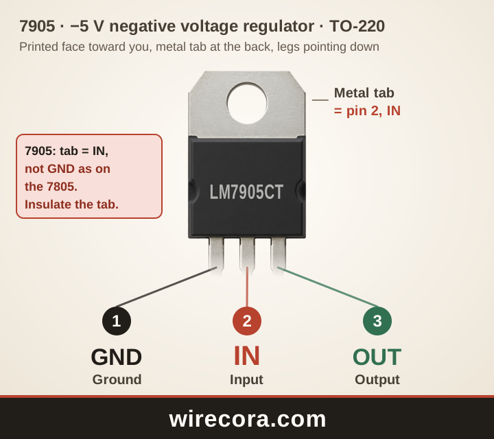
- Pin 1: Ground (GND)0 V, shared by the input and the output. On the 7905 the metal tab is not ground.
- Pin 2: Input (IN)The negative unsteady supply comes in here: about −7 V to −25 V. Also joined to the metal tab.
- Pin 3: Output (OUT)A steady −5 V comes out here.
Metal tab: joined to pin 2, the input, inside the part.
Check your part before wiring. Read the maker and the full part number printed on it, open that maker's datasheet, or test the legs with a multimeter's diode setting.
PNG 1440 × 1280 pixels, SVG to any size. Both keep the wirecora.com mark along the bottom.
Pinout table
Which leg of the 7905 is which?
| Pin | Name | What it does |
|---|---|---|
| 1 | Ground GND | 0 V, shared by the input and the output. On the 7905 the metal tab is not ground. |
| 2 | Input IN | The negative unsteady supply comes in here: about −7 V to −25 V. Also joined to the metal tab. |
| 3 | Output OUT | A steady −5 V comes out here. |
| Tab | Metal tab IN | Joined to pin 2, the input, so it carries the same voltage. Keep it away from other metal unless you mean it to touch. |
Key ratings
How much can the 7905 take?
From the Texas Instruments datasheet: LM79XX Series 3-Terminal Negative Regulators (SNOSBQ7C). Stay well inside these limits: they are the most the part takes, not what it should run at.
Open the Texas Instruments datasheet (PDF)Pin order by maker
Is every 7905 wired GND-IN-OUT?
TI's LM79XX datasheet and onsemi's MC7900 both number the legs 1 ground, 2 input, 3 output: GND-IN-OUT with the printed face toward you, and the metal tab is joined to pin 2, the input.
That is the trap. The positive 7805 and 7812 are IN-GND-OUT with the tab on ground; on the 7905 the first two legs swap jobs and the tab carries the negative input. Bolted to a grounded heatsink or metal case without an insulating pad and washer, the tab shorts the negative supply.
The makers differ on ratings: TI rates the LM7905 1.5 A, a −25 V maximum input and a 1.1 V typical dropout; onsemi rates the MC7905 1.0 A, −35 V and 1.3 V. We did not check ST's L7905, so read the datasheet of the part you have.
A first circuit
A steady −5 V from the minus side of a ±12 V supply
- The supply's 0 V (its common) to GND, its −12 V to IN.
- A 2.2 µF tantalum capacitor (or 25 µF aluminium) from IN to GND, close to the regulator. Its + end goes to GND, because IN is below 0 V.
- A 1 µF tantalum capacitor (or 25 µF aluminium) from OUT to GND, + end to GND. The 7905 needs it to stay stable.
- Take −5 V from OUT and 0 V from GND.
Unlike the 7805, the output capacitor is not optional. The extra voltage turns into heat: from −12 V at 0.5 A that is 3.5 W, which needs a heatsink, and the tab sits at −12 V, so mount it with an insulating pad and washer. With more than 100 µF on the output, add a 1N4001 with its striped end to OUT and its other end to IN.
7905 questions
What is the 7905 pinout?
With the printed face toward you and the legs pointing down, from left to right: ground, input, output (GND-IN-OUT). The metal tab is the input, not ground.
Is the 7905 wired like the 7805?
No. The 7805 is IN-GND-OUT with the tab on ground; the 7905 is GND-IN-OUT with the tab on the input. A 7905 put in a 7805's place has its input and ground swapped.
Can I bolt a 7905 to a grounded heatsink?
Only with an insulating pad under the tab and an insulating washer under the screw. The tab carries the negative input voltage, so bare contact with grounded metal shorts the negative supply.
What input voltage does a 7905 need?
Between about −7 V and −25 V (TI's maximum for the −5 V part; onsemi allows −35 V). At 1 A it needs about 1.1 to 1.3 V more than the 5 V it gives out, so −7 V leaves room.
Which way round do the capacitors go on a 7905?
The + end goes to GND on both, because IN and OUT are below 0 V. TI asks for 2.2 µF on the input when the supply's own capacitor is more than about 7.5 cm away, and 1 µF on the output for stability.
Can I use this pinout picture?
Yes. Download it as PNG or SVG and use it in notes, lessons or posts. The wirecora.com mark along the bottom stays in the picture.
Pin order and ratings from the Texas Instruments datasheet named above. Last reviewed .