Reverse a motor with one plain toggle switch
The wheel spins one way, the lever flips, and the same wheel spins back the other way. The moving dots on the wires jump from the left battery pack to the right one. There is no relay and no driver, only one three-lug toggle switch.
- 4 parts
- 4 wiring steps
- No code needed
- 3 V supply
Quick answer
The short version. Every pin is in the full wiring below.What you need
- TT gear motor
- Mini toggle switch, SPDT, three lugs
- 2 x AA battery holder, 3 V, two of them
- Four AA cells
How to wire it
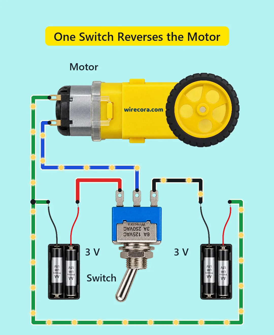
- Pack 1 plus (red) to the toggle's left lug.
- Pack 1 minus (black) to pack 2 plus (red) and to motor wire A.
- Pack 2 minus (black) to the toggle's right lug.
- Toggle middle lug (COM) to motor wire B.
Before you power it: Each pack is 3 V from two AA cells (6 V across both). Use alkaline AA only and never lithium-ion cells, because a switch that bridged both sides for a moment would short both packs. Keep fingers out of the wheel.
Parts list
- TT gear motor (3 to 6 V; about 150 mA with no load; 90 rpm at 3 V), with a wheel
- Mini toggle switch, SPDT, three lugs (MTS-102; rated 3 A at 250 V AC, no DC rating given)
- 2 x AA battery holder, 3 V, two of them (each with two AA cells; 6 V for both in series)
- Four AA cells (alkaline; never Li-ion)
Wiring, step by step
- Pack 1 plus (red) to the toggle's left lug.
- Pack 1 minus (black) to pack 2 plus (red) and to motor wire A. This joint is the middle of the two packs in series.
- Pack 2 minus (black) to the toggle's right lug.
- Toggle middle lug (COM) to motor wire B.
How it works
- The two packs sit in series, 3 V each. Their joint goes to one motor wire, and the toggle's middle lug goes to the other motor wire.
- When the switch joins COM to the left lug (pack 1), current leaves pack 1's plus, goes through the left lug and COM into motor B, through the motor to A, and back to pack 1's minus. The wheel turns one way.
- Flip the lever so COM joins the right lug (pack 2) and the current path changes: it leaves pack 2's plus at the joint, goes through the motor from A to B, then through COM and the right lug back to pack 2's minus.
- The current now flows through the motor the other way, so the motor sees +3 V in one position and -3 V in the other, from the same joint. A DC motor runs backwards when you swap its polarity.
What the video simplifies
- Moving dots are illustration; they show the path the current takes, not its real speed.
- Parts are drawn much larger than life, and the wheel is shown at 1.5 turns a second (90 rpm at 3 V).
- Which way the wheel turns depends on how the motor is connected; the direction in the Short is a drawing choice.
- The motor's stall current is not given in the source we used; 1 A is an assumption. Reversing at speed briefly pulls about 2 A (an estimate) because the motor's back-EMF adds to the supply. The switch has an AC rating of 3 A, with no DC rating given.
- Whether this toggle breaks one contact before it makes the other was not confirmed from a datasheet. A switch that bridged both sides would briefly short both packs, which is why the Short uses AA cells and not Li-ion.
- The reversal is eased for the eye, and its real time was not measured.
- Each pack only drives one direction, so the packs drain unevenly. 3 V is the bottom of this motor's range, so it runs slowly and fairly weakly.
- The wirecora.com print on the gearbox is our marking.
- This circuit was checked on paper, by simulation and from datasheets, not built.
You found this by searching. Here's the whole path.
- Read how it works
- See it work
- Build it
- Show it
Thirty seconds of video shows the circuit doing its job.
Each pack is 3 V from two AA cells (6 V across both). Use alkaline AA only and never lithium-ion cells, because a switch that bridged both sides for a moment would short both packs. Keep fingers out of the wheel.
Built it, or stuck halfway? Post a photo in the Wirecora Discord. Questions get an answer every day.
What to build next
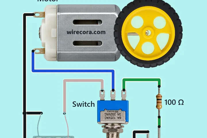 Same motorMotor lights an LED as it brakesA small wheel spins on a motor while the switch is on RUN.
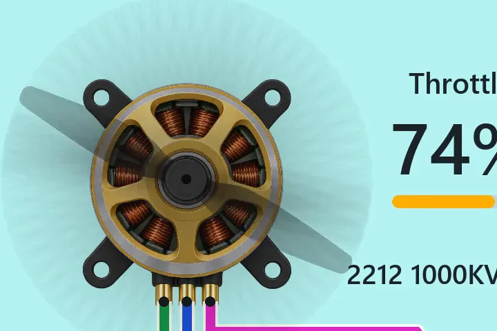 Next step: adds an ArduinoDrone motor speed control with an Arduino Nano, a pot and an ESCTurn a knob and a drone motor's propeller speeds up from 0 to 100 % throttle, then slows back down.
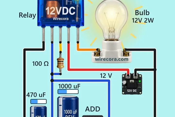 Something new: a relaySelf-blinking relay with a capacitorA 12 V bulb blinks fast, with nothing telling it when.