Self-blinking relay with a capacitor
A 12 V bulb blinks fast, with nothing telling it when. Press the ADD switch and the bulb blinks about three times slower. There is no chip and no transistor: the relay switches itself, and the capacitor decides how long each blink takes.
- 7 parts
- 6 wiring steps
- No code needed
- 12 V supply
Quick answer
The short version. Every pin is in the full wiring below.What you need
- 12 V relay
- 100 ohm resistor
- 470 uF 25 V electrolytic capacitor
- 1000 uF 25 V electrolytic capacitor
- Rocker switch
- 12 V 2 W bulb
- Regulated 12 V 2 A DC power supply
How to wire it
- Supply plus to the relay's COM contact.
- Relay NC contact to one end of the 100 ohm resistor.
- Other end of the 100 ohm resistor to one relay coil pin, the plus of the 470 uF capacitor and the rocker's switched tab (tab 2 as drawn).
- The rocker's other used tab (tab 1 as drawn) to the plus of the 1000 uF capacitor.
- Relay NO contact to one side of the bulb.
- Supply minus to the other relay coil pin, the minus (striped side) of both capacitors and the other side of the bulb.
Before you power it: Everything runs on 12 V DC from a regulated supply, but the capacitors are polarised: the striped side is minus, and a backwards one can burst. The bulb gets warm if you leave the demo running.
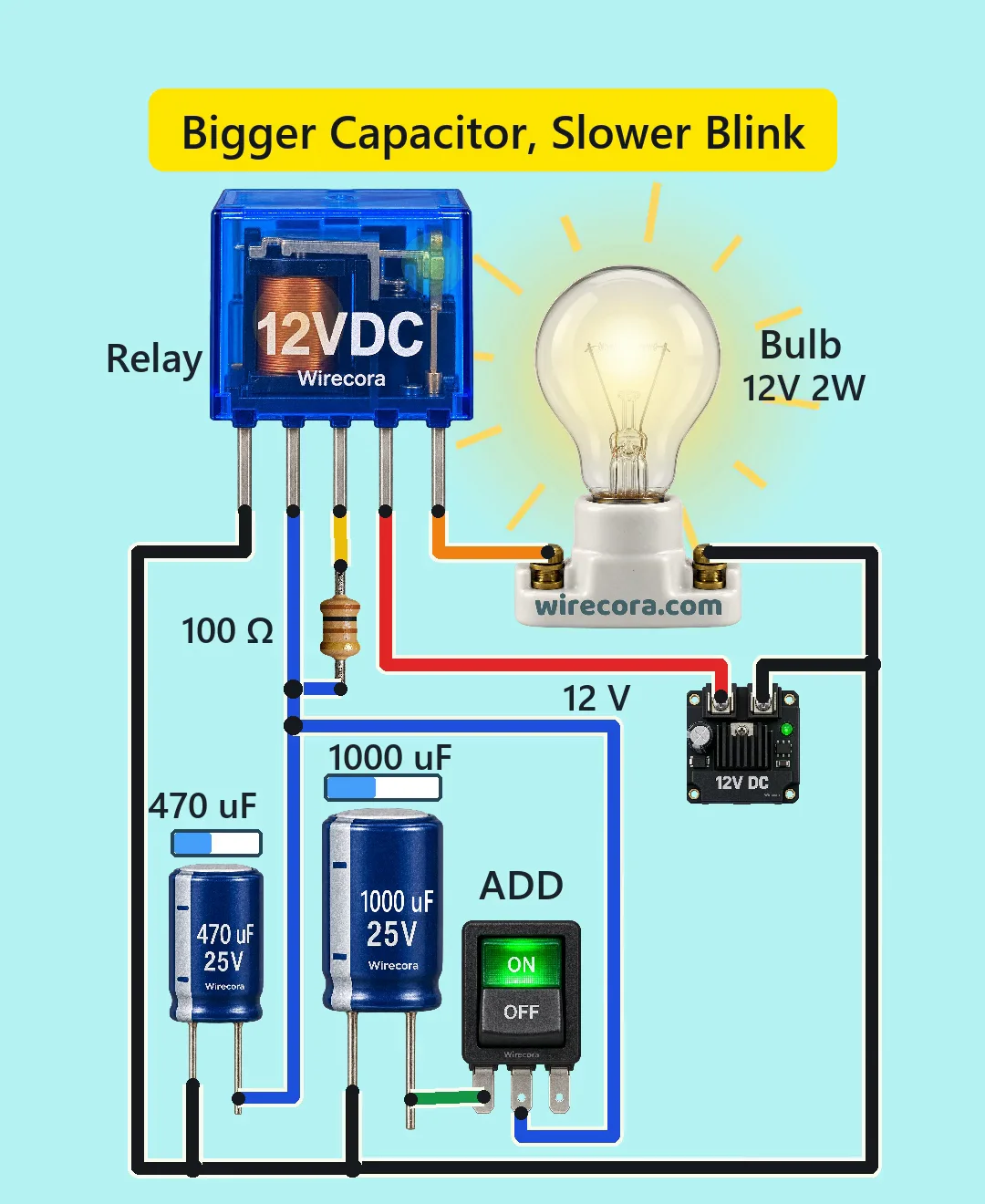
Parts list
- 12 V relay (400 ohm coil, 30 mA; contacts rated 10 A)
- 100 ohm resistor, 1/2 W, from the relay's NC contact to the coil
- 470 uF 25 V electrolytic capacitor, across the relay coil
- 1000 uF 25 V electrolytic capacitor, switched in with the ADD rocker
- Rocker switch (the one in the Short is rated 6 A; its green and red glow only show ON and OFF)
- 12 V 2 W bulb (a small, fast filament)
- Regulated 12 V 2 A DC power supply
Wiring, step by step
- Supply plus to the relay's COM contact.
- Relay NC contact to one end of the 100 ohm resistor.
- Other end of the 100 ohm resistor to one relay coil pin, the plus of the 470 uF capacitor and the rocker's switched tab (tab 2 as drawn).
- The rocker's other used tab (tab 1 as drawn) to the plus of the 1000 uF capacitor. The third tab is for the switch's own lamp and stays free, so that lamp stays dark.
- Relay NO contact to one side of the bulb.
- Supply minus to the other relay coil pin, the minus (striped side) of both capacitors and the other side of the bulb.
How it works
- At the start the relay is released, so COM is joined to NC. Current flows from the supply through NC and the 100 ohm resistor into the coil and the capacitor, and the capacitor charges.
- When the capacitor and coil reach about 8 V in the simulation, the coil pulls in. NC opens and NO closes, so the bulb lights.
- With NC open, the supply no longer feeds the coil. The charged capacitor keeps the coil going until it runs down to about 2 V, then the relay drops. NC closes again, the bulb goes dark and the capacitor recharges.
- Pressing ADD puts the 1000 uF capacitor in parallel with the 470 uF one: 1470 uF in all, about three times the charge, so each part of the cycle takes about three times as long.
- In the simulation the blink period goes from about 0.35 s to about 1.03 s, a ratio of 2.97.
What the video simplifies
- The blink times are simulated with typical relay thresholds (pull in at 8 V, drop out at 2 V). A real relay can be up to about 1.7 times faster or slower, but the factor of three stays.
- The charge bars over the capacitors are added for clarity. The light rays and glow round the bulb are drawn and turn. The parts are drawn large.
- The bulb is a small 12 V 2 W one. The Short fades it faster than real: a real filament takes about 30 to 60 ms to fade, not 10, and keeps a dull orange glow in the fast gaps. A bigger bulb only dims there.
- The press of ADD is timed to a pull-in so the two capacitors hold the same voltage. Press at another moment and only that one blink changes. The first press then joins capacitors at different voltages: 13 to 32 A for about 0.1 to 0.2 ms in the simulation, harmless but above the rocker's rating.
- A relay at the far end of its datasheet (pull-in up to 9 V) may not start with 100 ohm. Use a steady 12 V supply and a 400 ohm coil; a lower-ohm coil may never pull in.
- This relay is rated for 30 switchings a minute under load. Here it runs at about 173 a minute fast and 58 slow, so this is a demo, not something to leave running for hours.
- The relay pins are drawn in the order coil, coil, NC, COM, NO. A real relay's pins sit elsewhere, so check its datasheet.
- This circuit was checked by simulation and datasheets, not built.
You found this by searching. Here's the whole path.
- Read how it works
- See it work
- Try it on the board
- Build it
- Show it
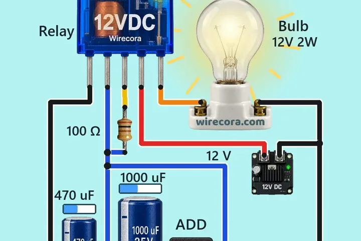
Thirty seconds of video shows the circuit doing its job. Then this whole circuit is on the wiring board. Wire it there first and watch it work before you touch a real part.
Everything runs on 12 V DC from a regulated supply, but the capacitors are polarised: the striped side is minus, and a backwards one can burst. The bulb gets warm if you leave the demo running.
Built it, or stuck halfway? Post a photo in the Wirecora Discord. Questions get an answer every day.
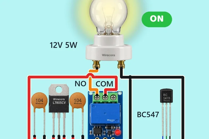 Same relay + lampTouch switch lamp
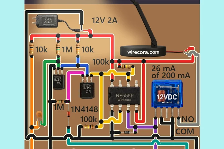 Next step: adds a 555 timerClap switch lamp with a 555
 Something new: a motorCar window switch, no relay