Touch switch lamp
A finger taps a red TTP223 touch pad. A relay clicks and a 12 V lamp turns on and stays on. The next tap turns it off. One 12 V battery runs the whole circuit.
- 10 parts
- 6 wiring steps
- No code needed
- 12 V supply
Quick answer
The short version. Every pin is in the full wiring below.What you need
- 12 V 7 Ah battery
- 12 V 5 W lamp with holder
- TTP223 touch module, set to toggle mode
- 5 V one-channel relay module, low-level trigger
- BC547 NPN transistor
- 1 kilohm resistor
- 7805 regulator
- 2 x 100 nF ceramic capacitors
- 1 A fuse at the battery + terminal
- Hook-up wire
How to wire it
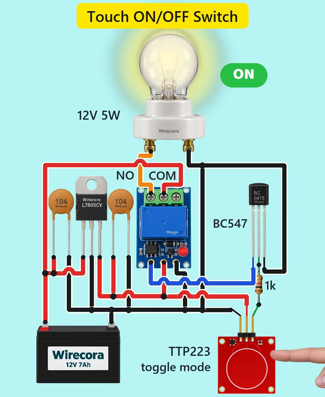
- Battery + goes to the 7805 input, to the first capacitor and to relay COM.
- The 7805 output (5 V) goes to the second capacitor, to the TTP223 VCC and to the relay VCC.
- TTP223 signal goes through the 1 kilohm resistor to the BC547 base.
- The BC547 collector goes to the relay IN pin.
- Relay NO goes to one lamp terminal.
- Pin order differs between TTP223 boards.
Before you power it: 12 V DC, but a battery can push a very large current into a shorted wire. Put a 1 A fuse at the battery + terminal. Do not replace the 12 V lamp with a mains bulb: this relay board must not switch mains in a home build.
Parts list
- 12 V 7 Ah battery
- 12 V 5 W lamp with holder
- TTP223 touch module, set to toggle mode
- 5 V one-channel relay module, low-level trigger (SRD-05VDC-SL-C type, IN active LOW)
- BC547 NPN transistor
- 1 kilohm resistor
- 7805 regulator (L7805CV)
- 2 x 100 nF ceramic capacitors (marked 104), one on the 7805 input and one on its output
- 1 A fuse at the battery + terminal (recommended for a real build)
- Hook-up wire
Wiring, step by step
- Battery + goes to the 7805 input, to the first capacitor and to relay COM. Battery - is the common ground for everything.
- The 7805 output (5 V) goes to the second capacitor, to the TTP223 VCC and to the relay VCC. The 7805 middle pin goes to ground.
- TTP223 signal goes through the 1 kilohm resistor to the BC547 base. The BC547 emitter goes to ground.
- The BC547 collector goes to the relay IN pin.
- Relay NO goes to one lamp terminal. The other lamp terminal goes to ground. Relay NC stays unused.
- Pin order differs between TTP223 boards. It is drawn here as GND, VCC, SIG. The small TOUCH board is VCC, I/O, GND. Follow the print on yours. The relay header here is IN, VCC, GND. Many boards print VCC, GND, IN, so check yours too.
How it works
- In toggle mode (close the toggle solder pad, B on most boards, and leave the other open) the TTP223 output goes HIGH on one touch and LOW on the next.
- The 5 V relay module switches on when its IN pin is pulled LOW. The BC547 turns the touch signal around. Output HIGH turns the transistor on, which pulls IN low and the relay comes on.
- The relay's COM and NO contacts switch the lamp: 0.42 A on a 10 A contact.
- The next touch makes the output LOW. The BC547 turns off, IN goes back high, the relay drops out and the lamp goes off.
- The 7805 makes the 5 V for the touch module and the relay from the same 12 V battery. The 5 V part draws about 85 mA, so the 7805 gets about 0.6 W and needs no heat sink.
- The base current is about 4.3 mA through the 1 kilohm resistor, far below what the BC547 needs and can take.
What the video simplifies
- The parts are drawn at different scales. The lamp is big and the BC547 is small.
- The ring on the pad is a visual cue. Nothing glows on a real pad.
- The touch response (about 60 ms) and the lamp warm-up are smoothed. The ON/OFF badge is a caption, not a part.
- A side-view hand taps a board seen from above.
- The 7805 datasheet asks for 0.33 uF on the input. 100 nF on both sides is the usual hobby choice.
- The fuse is recommended for a real build. It is not drawn.
- The viral original switches a 230 V mains bulb. This version uses a 12 V lamp so it is safe to build.
- Checked by simulation and datasheets only. It was not built.
You found this by searching. Here's the whole path.
- Read how it works
- See it work
- Build it
- Show it
Thirty seconds of video shows the circuit doing its job.
12 V DC, but a battery can push a very large current into a shorted wire. Put a 1 A fuse at the battery + terminal. Do not replace the 12 V lamp with a mains bulb: this relay board must not switch mains in a home build.
Built it, or stuck halfway? Post a photo in the Wirecora Discord. Questions get an answer every day.
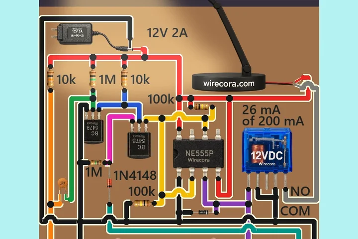 Same relay + lampClap switch lamp with a 555
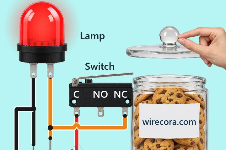 Next step: adds a buzzerCookie jar lid alarm
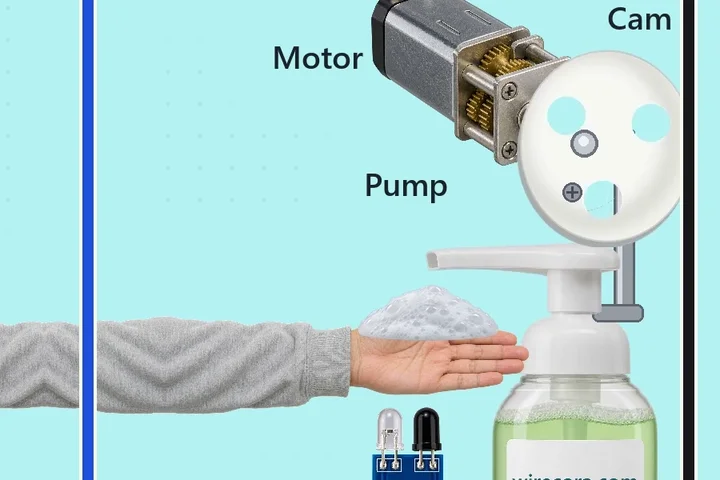 Something new: a pumpTouchless foam soap dispenser