Touchless foam soap dispenser
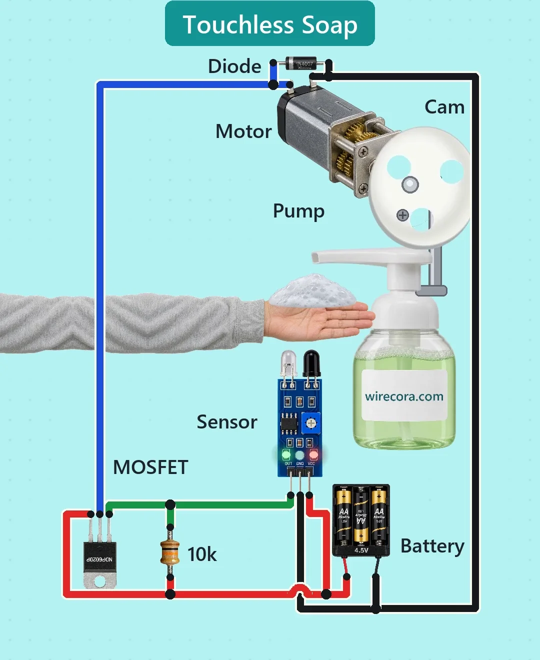
You hold a hand under the nozzle. An infrared sensor sees the palm and switches a MOSFET on. The MOSFET runs a small gear motor. A cam on the motor shaft presses the foam pump once per turn, so foam drops into your hand. Take the hand away and the motor stops.
- 7 parts
- 5 wiring steps
- No code needed
- 4.5 V supply
Quick answer
The short version. Every pin is in the full wiring below.What you need
- 3 x AA batteries in a holder, in series
- FC-51 infrared obstacle sensor module
- Logic-level P-channel MOSFET
- 10k resistor
- 1N4007 diode
- 6 V micro metal gear motor
- A foam soap bottle with a pump head
How to wire it
- Battery plus goes to the sensor's VCC pin, to the MOSFET source (S) and to one end of the 10k resistor.
- The sensor's OUT pin goes to the MOSFET gate (G) and to the other end of the 10k resistor.
- The MOSFET drain (D, the middle leg of the NDP6020P) goes to one motor tab and to the band (cathode) of the 1N4007.
- Battery minus goes to the sensor's GND pin, to the other motor tab and to the plain end (anode) of the 1N4007.
- Fit the cam on the motor shaft so it presses the pump head down once per turn.
Before you power it: Low voltage only (4.5 V from three AA cells). A battery pack has no fuse, so keep the wires insulated and keep the bare ends apart. Keep the electronics dry and away from the soap.
Parts list
- 3 x AA batteries in a holder, in series (4.5 V)
- FC-51 infrared obstacle sensor module (3 pins: OUT, GND, VCC)
- Logic-level P-channel MOSFET, for example NDP6020P, or any equivalent with RDS(on) given at -4.5 V or lower
- 10k resistor
- 1N4007 diode
- 6 V micro metal gear motor, 298:1, with a cam on its shaft
- A foam soap bottle with a pump head
Wiring, step by step
- Battery plus goes to the sensor's VCC pin, to the MOSFET source (S) and to one end of the 10k resistor.
- The sensor's OUT pin goes to the MOSFET gate (G) and to the other end of the 10k resistor. So the 10k sits between the gate and the source.
- The MOSFET drain (D, the middle leg of the NDP6020P) goes to one motor tab and to the band (cathode) of the 1N4007.
- Battery minus goes to the sensor's GND pin, to the other motor tab and to the plain end (anode) of the 1N4007. The diode sits across the motor.
- Fit the cam on the motor shaft so it presses the pump head down once per turn.
How it works
- With no hand in front of it the sensor leaves OUT open. The 10k resistor holds the gate at the same voltage as the source, so the MOSFET is off and the motor has no supply.
- A palm in front of the sensor makes the sensor pull OUT low. The gate then sits about 4 V below the source, the P-channel MOSFET switches on and the motor runs from the 4.5 V pack.
- The cam presses the pump head down once per turn and lets it spring back. The drawn motor turns about 71 rpm, so you get about one dose of foam every 0.85 s while the hand stays there.
- Hand away: OUT is released, the 10k pulls the gate back up to the source, the MOSFET switches off and the motor stops. The 1N4007 across the motor takes the voltage kick that the motor makes when it switches off.
- Set the sensor's trimmer so it sees a palm close by but not the nozzle above it.
What the video simplifies
- The sensor's low output level (taken as about 0.35 V) and its output current are assumed. The datasheet figures for this module were not read.
- The motor figures (about 71 rpm and the push at 4.5 V) are worked out from the maker's 6 V figures. They are not measured. The stall current (1.2 A) is assumed.
- The motor and the cam are drawn much bigger than real, and the pump head travels about 14 % of the bottle's height. A real foam pump travels much less.
- The hand is slowed down and drawn a little small next to the bottle. The foam is a picture, not a simulation.
- Real dispensers often use a sealed motor pump and time one dose. This one pumps for as long as the hand is there, and the cam can stop half-pressed. A stop switch on the cam would park it.
- The sensor sits in the base looking up. In a real build put it a little to the side so drips miss it. If motor noise makes the sensor flicker, try a 100 µF capacitor across its supply.
- There is no fuse on the three AA cells. This circuit was checked against datasheets and was not built.
You found this by searching. Here's the whole path.
- Read how it works
- See it work
- Build it
- Show it
Thirty seconds of video shows the circuit doing its job.
Low voltage only (4.5 V from three AA cells). A battery pack has no fuse, so keep the wires insulated and keep the bare ends apart. Keep the electronics dry and away from the soap.
Built it, or stuck halfway? Post a photo in the Wirecora Discord. Questions get an answer every day.
What to build next
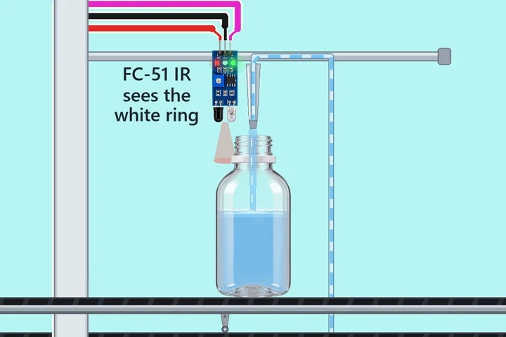 Same pump + motorArduino bottle filler with one relayA belt brings an empty bottle.
 Next step: adds a 555 timerStep-pad porch reaper with a 555 timer and a worm gear motorStep on the STEP HERE mat and the hooded reaper by the door lunges at you twice with glowing red eyes, then leans back and waits for the next visitor.
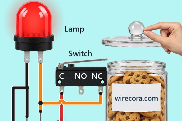 Something new: a buzzerCookie jar lid alarmA little lever under the glass lid keeps this cookie jar quiet.