Motor lights an LED as it brakes
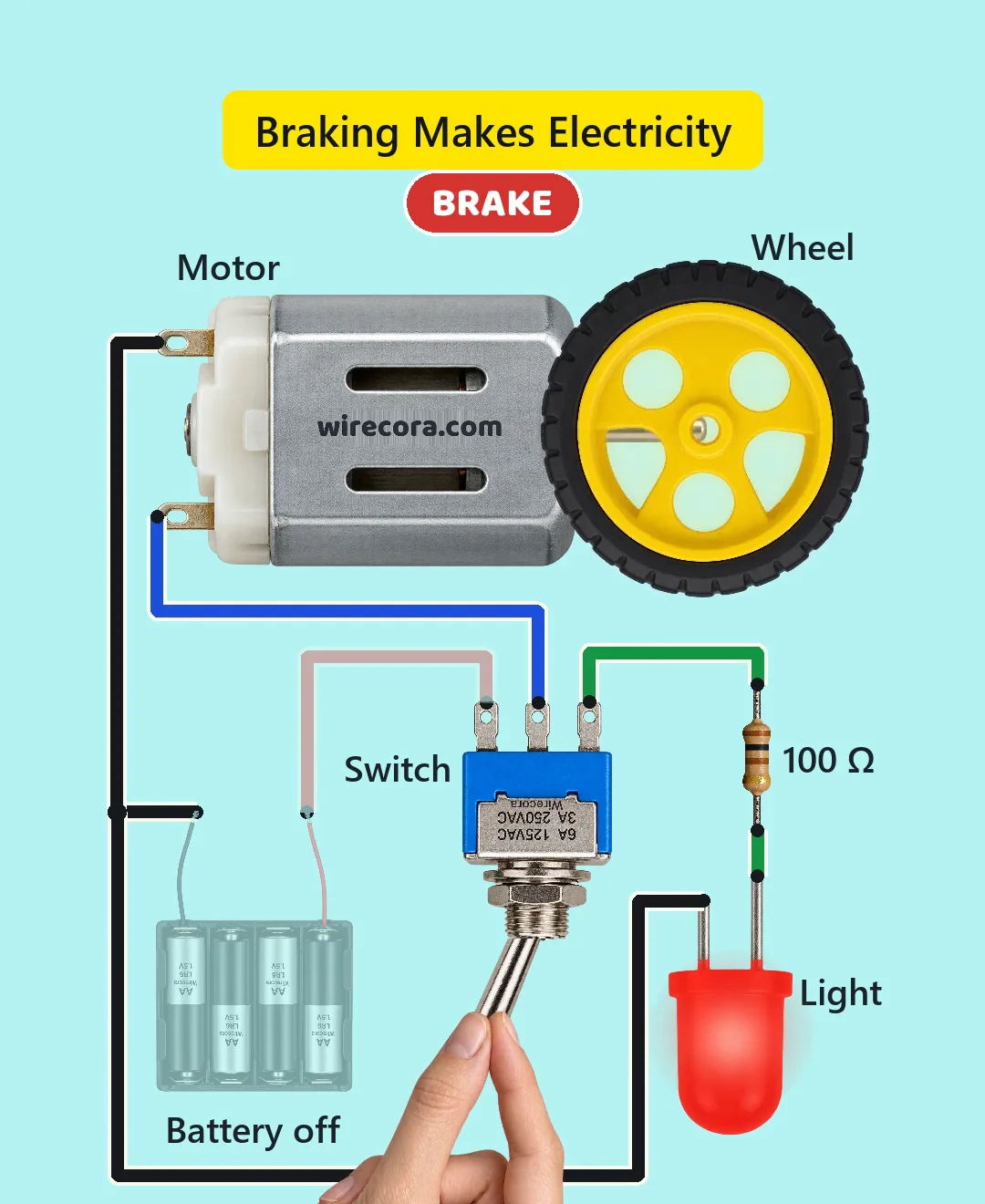
A small wheel spins on a motor while the switch is on RUN. Flip the switch to BRAKE and the battery is out of the circuit, but the wheel keeps turning and the same motor lights a red LED. The light fades as the wheel slows down.
- 6 parts
- 5 wiring steps
- No code needed
- 6.4 V supply
Quick answer
The short version. Every pin is in the full wiring below.What you need
- 6 V DC motor, 130 size
- Small wheel on the motor shaft
- Toggle switch with three lugs
- 100 ohm resistor in series with the LED
- Red LED
- 4 x AA battery holder
How to wire it
- Battery pack plus (red lead) to the toggle's RUN lug.
- Toggle centre lug (COM) to motor terminal B.
- Toggle BRAKE lug to one end of the 100 ohm resistor.
- Other end of the 100 ohm resistor to the LED's longer lead (the anode).
- Battery pack minus, motor terminal A and the LED's shorter lead (the cathode) all to one common minus wire.
Before you power it: Everything runs on a 6.4 V battery pack. Keep fingers away from the spinning wheel, and do not use a smaller resistor than 100 ohm: the LED would then go over its current limit when you flip to BRAKE.
Parts list
- 6 V DC motor, 130 size (not the 3 V toy type: by a rough estimate it would push about 35 mA into the LED, over its limit)
- Small wheel on the motor shaft, 60 mm across and about 5 g (an assumed size and weight)
- Toggle switch with three lugs, RUN, centre and BRAKE (the one in the Short is an MTS-102)
- 100 ohm resistor in series with the LED
- Red LED (the longer lead goes toward the resistor)
- 4 x AA battery holder, 6.4 V with fresh alkaline cells
Wiring, step by step
- Battery pack plus (red lead) to the toggle's RUN lug.
- Toggle centre lug (COM) to motor terminal B.
- Toggle BRAKE lug to one end of the 100 ohm resistor.
- Other end of the 100 ohm resistor to the LED's longer lead (the anode).
- Battery pack minus, motor terminal A and the LED's shorter lead (the cathode) all to one common minus wire.
How it works
- On RUN the battery feeds the motor through the toggle. In the 2 seconds of RUN shown the wheel speeds up to about 7,500 rpm; left on RUN it would settle near 9,700 rpm.
- A spinning motor also makes a voltage of its own, and that voltage rises with speed. Flip to BRAKE and the toggle takes the battery away and joins the motor to the resistor and LED instead.
- The motor's own voltage pushes current out of terminal B, through the toggle, the 100 ohm resistor and the LED in its forward direction, and back to terminal A. The LED lights.
- As the wheel slows the voltage falls, so the current and the light fall with it. The roughly 7,500 rpm drops to about 3,800 rpm over the 4 seconds of BRAKE shown.
- Flip back to RUN and the battery drives the wheel up to speed again.
What the video simplifies
- Nothing charges here. A real electric car sends that power back into its battery through electronics, and pulls much harder. In the simulation the LED takes about a fifth of the drag at the start and about an eighth overall; the rest of the slowing is plain friction.
- The wheel is drawn much slower than the real roughly 7,500 rpm falling to 3,800 rpm, with the ratio kept. It is drawn smaller than 60 mm next to the motor and turned to face you; on a real shaft you would see it edge-on.
- The battery and its red wire fade on screen only to show that they are out of the circuit in BRAKE; on a real board the pack just stays connected to the toggle. The LED glow is drawn. The LED and the battery are drawn at different scales.
- The wheel size and weight are assumed. A heavy rubber tyre coasts longer and the light would fade much more slowly.
- With 100 ohm the LED peaks at 19.3 mA on the 2 second cycle shown. If you keep the switch on RUN until the motor reaches full speed first, the peak is 29.4 mA in simulation, right at the LED's usual 30 mA limit.
- The toggle's datasheet gives only AC ratings (MTS-102: 3 A at 250 V AC). Here it carries under 0.5 A at 6.4 V DC.
- This circuit was checked by simulation and datasheets, not built.
You found this by searching. Here's the whole path.
- Read how it works
- See it work
- Build it
- Show it
Thirty seconds of video shows the circuit doing its job.
Everything runs on a 6.4 V battery pack. Keep fingers away from the spinning wheel, and do not use a smaller resistor than 100 ohm: the LED would then go over its current limit when you flip to BRAKE.
Built it, or stuck halfway? Post a photo in the Wirecora Discord. Questions get an answer every day.
What to build next
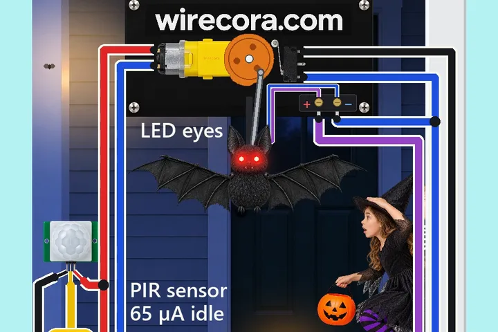 Same motorFlapping porch bat with a motion sensor, a TIP120 and a TT gear motorTrick-or-treaters walk up to the door, a motion sensor sees them, and the big bat under the porch roof lights its red eyes and beats its wings, about two a second.
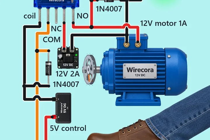 Next step: adds a relayFoot pedal motor switch with a 5 V relay and a 12 V motorStep on the pedal and the 12 V motor runs and the green RUN lamp lights.
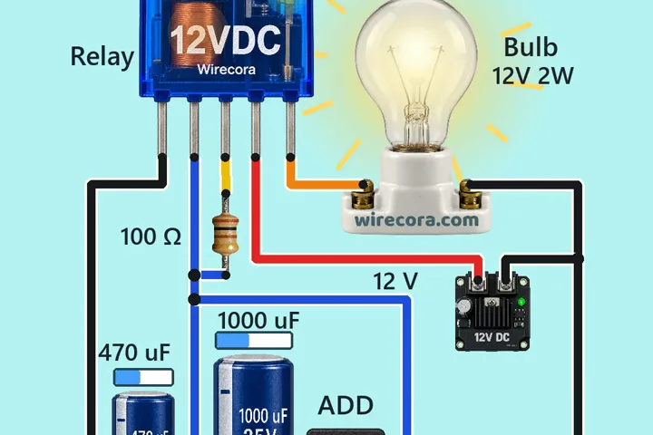 Something new: a relaySelf-blinking relay with a capacitorA 12 V bulb blinks fast, with nothing telling it when.