Stepper motor that reverses when you flip a switch
Flip the toggle switch and the stepper motor turns the other way. An Arduino Uno steps a 28BYJ-48 motor through a ULN2003 driver board, and a switch on pin D2 tells the sketch which way to go. Flip the switch back and the motor turns the first way again.
- 6 parts
- 6 wiring steps
- Arduino code
- 5 V supply
Quick answer
The short version. Every pin is in the full wiring below.What you need
- Arduino Uno R3
- 28BYJ-48 5 V unipolar stepper motor
- ULN2003 stepper driver board
- Toggle switch
- Regulated 5 V 2 A supply
- Jumper wires
How to wire it
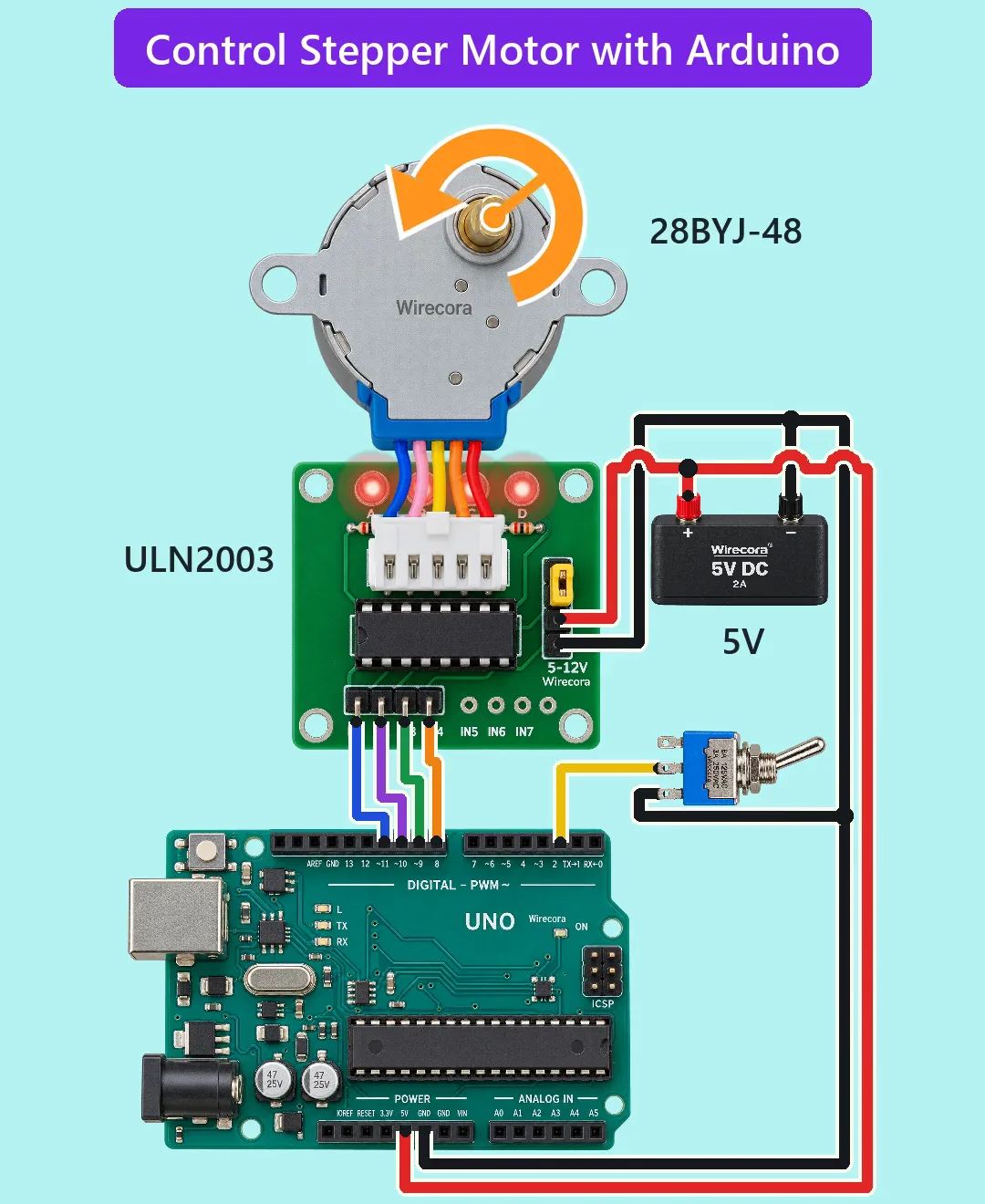
- Supply plus to the ULN2003 board's + pin, which is the second pin from the bottom of the power pins.
- Supply plus also to the Uno 5V pin.
- Uno D11 to board IN1, D10 to IN2, D9 to IN3 and D8 to IN4.
- Motor plug into the board's socket.
- Toggle switch COM lug to Uno D2.
- Do not plug in USB while the supply is connected to the 5V pin.
Before you power it: Everything runs on 5 V from a regulated supply, and the whole circuit draws about 0.21 A. Use the 5V pin only with a regulated 5 V supply, nothing on VIN or the barrel jack, and no USB while the supply is connected.
Parts list
- Arduino Uno R3 (5 V)
- 28BYJ-48 5 V unipolar stepper motor (50 ohm per coil, gearbox 1/64, 5-pin plug with the red wire as the common +5 V)
- ULN2003 stepper driver board (it has a socket for the motor plug, four inputs IN1 to IN4, power pins + and -, and four LEDs)
- Toggle switch (SPDT, three lugs A, COM and B)
- Regulated 5 V 2 A supply
- Jumper wires
Wiring, step by step
- Supply plus to the ULN2003 board's + pin, which is the second pin from the bottom of the power pins. Supply minus to the board's - pin, the lowest one.
- Supply plus also to the Uno 5V pin. Supply minus also to an Uno GND pin on the power header. All grounds are joined. VIN stays empty.
- Uno D11 to board IN1, D10 to IN2, D9 to IN3 and D8 to IN4.
- Motor plug into the board's socket. The plug only fits one way round.
- Toggle switch COM lug to Uno D2. Toggle switch B lug to GND. The A lug stays unconnected.
- Do not plug in USB while the supply is connected to the 5V pin. Upload the sketch first, unplug USB, then connect the supply.
How it works
- The sketch sets D2 as INPUT_PULLUP, so a resistor inside the Uno pulls D2 up to 5 V. With the lever on the open side (COM to A, and A goes nowhere) D2 reads HIGH.
- Moving the lever to the B side joins D2 to GND, so D2 reads LOW.
- Each pass of loop() reads D2 and moves one step along a four-step pattern: HIGH goes forward, LOW goes backward. The pattern switches on two coils at a time (AB, BC, CD, DA).
- The Uno pins only drive the ULN2003 inputs (about 1.3 mA each). The ULN2003 switches the motor coils, about 82 mA each, so two coils on draw about 164 mA.
- The sketch waits 1953 microseconds per step, which is 512 steps a second. The gearbox needs 2048 steps for one turn of the shaft, so the shaft turns at 15 RPM (90 degrees a second).
The code: stepper_flip_reverse.ino
The Arduino code for this circuit is in the Wirecora Discord, in the channel #arduino-code (owner’s choice, 14 October 2026: the code lives where you can ask about it). It is a plain .ino file you can download there.
The sketch the Short was animated from. It needs no library. It was checked by simulation and has not been run on a real board; if the motor stutters or stalls at 15 RPM, make STEP_US bigger (for 10 RPM use 2930).
What the video simplifies
- The orange arrow is a marker on the shaft. It turns at the real speed, and its head swaps ends at each flip.
- The motor leads are drawn shorter than the real ones (23 to 25 cm) so the motor fits above the board.
- The Short shows the reversal as instant. A real motor may lose a step or two when it reverses at full speed; 10 RPM is the safer setting.
- The four board LEDs look steadily lit because each one switches on and off 128 times a second. The LED colour is drawn red, and the click and motor sounds are made up.
- A real gearbox is about 1/63.7, so the real speed is about 15.07 RPM, not exactly 15.
- No text in the Short says which way the shaft turns, because that depends on the gearbox. Swap the pattern direction in the sketch if you want the other way for the switch position.
- The Short follows the original in using the pin order D11 to D8 for IN1 to IN4, so the wires do not cross. The sketch uses the same order.
- This circuit was checked by simulation (ngspice) and against the datasheets, not built.
You found this by searching. Here's the whole path.
- Read how it works
- See it work
- Build it
- Show it
Thirty seconds of video shows the circuit doing its job.
Everything runs on 5 V from a regulated supply, and the whole circuit draws about 0.21 A. Use the 5V pin only with a regulated 5 V supply, nothing on VIN or the barrel jack, and no USB while the supply is connected.
Built it, or stuck halfway? Post a photo in the Wirecora Discord. Questions get an answer every day.
What to build next
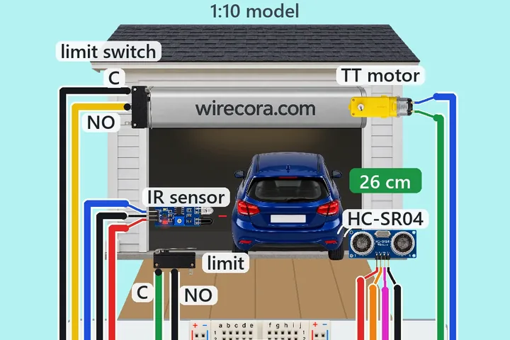 Same Arduino + motorModel garage door that opens for a car, with an Arduino Nano, an HC-SR04 and an L298NA car rolls up the driveway.
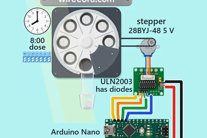 Next step: adds a buzzerDaily pill dispenserAt 8:00 a chime sounds, the wheel turns one slot and a single white tablet drops into the cup.
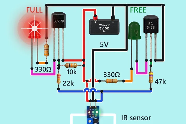 Something new: an IR sensorSmart parking system with two LEDsDrive the toy car into the bay and the red FULL LED lights while the green FREE LED goes dark.