Smart parking system with two LEDs
Drive the toy car into the bay and the red FULL LED lights while the green FREE LED goes dark. An FC-51 IR obstacle module watches the end of the bay and pulls its OUT pin low when the car comes within about 4 cm. Two transistors turn that one signal into exactly one lit LED. When the car backs out, green FREE lights again.
- 11 parts
- 7 wiring steps
- No code needed
- 5 V supply
Quick answer
The short version. Every pin is in the full wiring below.What you need
- 5 V DC power supply, 2 A
- FC-51 IR obstacle module
- BC557B PNP transistor
- BC547B NPN transistor
- 5 mm red LED
- 5 mm green LED
- 330 ohm resistor
- 22 k resistor, from OUT to the BC557 base
- 47 k resistor, from OUT to the BC547 base
- 10 k resistor, from the BC557 base to +5 V
- Jumper wires
How to wire it
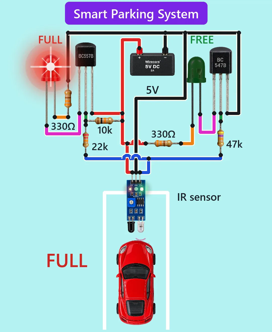
- Supply plus (red) to the module's VCC, the BC557 emitter (E), one end of the 10 k resistor and one end of the green LED's 330 ohm resistor.
- Supply minus (black) to the module's GND, the BC547 emitter (E) and one end of the red LED's 330 ohm resistor.
- Module OUT (blue) to one end of the 22 k resistor and one end of the 47 k resistor.
- The other end of the 22 k resistor to the BC557 base (B).
- BC557 collector (C) to the red LED's long lead (anode).
- The other end of the 47 k resistor to the BC547 base (B).
- Supply plus through the other 330 ohm resistor to the green LED's long lead (anode).
Before you power it: Everything runs on 5 V and the currents are tiny: about 9 mA in the lit LED and about 45 mA from the supply. Keep the 330 ohm resistors in series with the LEDs, and connect the supply plus and minus the right way round.
Parts list
- 5 V DC power supply, 2 A
- FC-51 IR obstacle module (LM393, works from 3.3 to 5 V, OUT goes LOW when it sees something, pins OUT, GND and VCC)
- BC557B PNP transistor (pins C, B, E; flat face toward you, left to right)
- BC547B NPN transistor (pins C, B, E; flat face toward you, left to right)
- 5 mm red LED (the FULL light)
- 5 mm green LED (the FREE light)
- 330 ohm resistor, two of them, one in series with each LED
- 22 k resistor, from OUT to the BC557 base
- 47 k resistor, from OUT to the BC547 base
- 10 k resistor, from the BC557 base to +5 V
- Jumper wires
Wiring, step by step
- Supply plus (red) to the module's VCC, the BC557 emitter (E), one end of the 10 k resistor and one end of the green LED's 330 ohm resistor.
- Supply minus (black) to the module's GND, the BC547 emitter (E) and one end of the red LED's 330 ohm resistor. All grounds are joined.
- Module OUT (blue) to one end of the 22 k resistor and one end of the 47 k resistor.
- The other end of the 22 k resistor to the BC557 base (B). The other end of the 10 k resistor also goes to that base.
- BC557 collector (C) to the red LED's long lead (anode). The red LED's short lead (cathode) to the 330 ohm resistor that goes to minus.
- The other end of the 47 k resistor to the BC547 base (B).
- Supply plus through the other 330 ohm resistor to the green LED's long lead (anode). The green LED's short lead (cathode) to the BC547 collector (C).
How it works
- The module's OUT pin is pulled up to +5 V inside the module, so with an empty bay OUT is high, about 4.4 V.
- That high OUT pushes a small current (about 79 microamps) through the 47 k resistor into the BC547 base. The BC547 turns on and the green LED lights through its 330 ohm resistor, at about 9 mA.
- At the same time the 10 k resistor holds the BC557 base up near +5 V, so the BC557 stays off and the red LED stays dark.
- When the car comes within about 4 cm, the module pulls OUT down to about 0.2 V. The BC547 base loses its current, so it turns off and the green LED goes dark.
- The low OUT now draws current out of the BC557 base through the 22 k resistor (about 0.11 mA). The BC557 turns on and the red LED lights at about 9 mA. When the car leaves, OUT goes high again and green returns.
What the video simplifies
- This is a toy car: the sensor is set to trigger at about 4 cm. The FC-51 really works from about 2 to 30 cm, and how far it sees depends on the colour of the surface.
- The infrared waves are drawn as arcs, but infrared is invisible.
- The 10 k pull-up inside the module and which of its two small on-board LEDs is the obstacle light are assumed from the usual FC-51 circuit, not read from the module.
- The common guide for this project uses 10 k base resistors on both transistors. With those the module output only rises to about 3.4 V when the bay is free and both LEDs glow together. This version uses 22 k and 47 k and adds the 10 k from base to emitter on the BC557, so exactly one LED is on.
- The words FREE and FULL beside the bay, the LED glow, the quick fade when the LEDs switch (really a few milliseconds) and the sounds are added for the video. The sounds are synthesised.
- This circuit was checked by simulation (ngspice) and against the datasheets, not built.
You found this by searching. Here's the whole path.
- Read how it works
- See it work
- Try it on the board
- Build it
- Show it
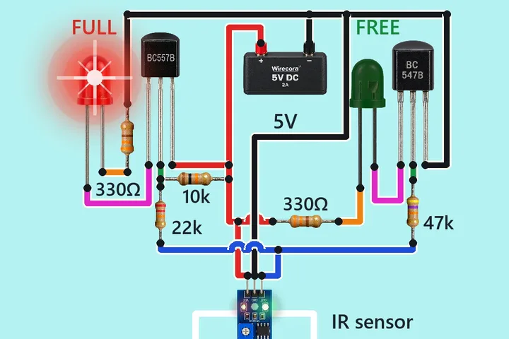
Thirty seconds of video shows the circuit doing its job. Then this whole circuit is on the wiring board. Wire it there first and watch it work before you touch a real part.
Everything runs on 5 V and the currents are tiny: about 9 mA in the lit LED and about 45 mA from the supply. Keep the 330 ohm resistors in series with the LEDs, and connect the supply plus and minus the right way round.
Built it, or stuck halfway? Post a photo in the Wirecora Discord. Questions get an answer every day.
What to build next
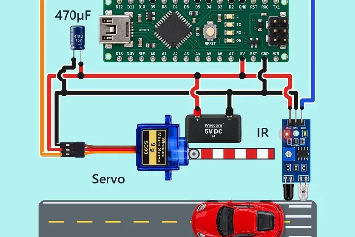 Same IR sensorToy car barrier gateA toy car drives under an IR sensor, the green LED comes on and a servo swings the barrier open.
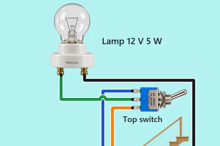 Something new: a lampStaircase light: two switches, one lampFlip either of two switches and the lamp changes: on becomes off, off becomes on.
 Same IR sensorHelmet that closes its own visorYou lower the helmet onto your head and the visor swings down by itself.