Toy car barrier gate
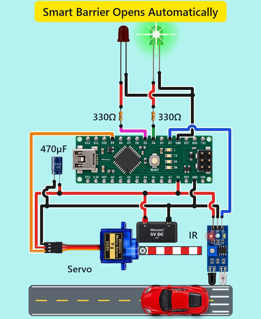
A toy car drives under an IR sensor, the green LED comes on and a servo swings the barrier open. Two seconds after the car has gone the barrier closes and the red LED returns.
- 7 parts
- 6 wiring steps
- Arduino code
- 5 V supply
Quick answer
The short version. Every pin is in the full wiring below.What you need
- 5 V 2 A power supply
- Arduino Nano
- IR obstacle module
- SG90 servo
- 5 mm red LED and 5 mm green LED
- 330 ohm resistor, two of them, one for each LED
- 470 uF electrolytic capacitor across the 5 V supply next to the servo leads
How to wire it
- Supply plus to the Nano's 5V pin, the IR module's VCC, the servo's red lead and the plus of the 470 uF capacitor.
- Supply minus to the Nano's GND, the IR module's GND, the servo's brown lead, the capacitor's minus and both LED cathodes.
- IR module OUT to D2.
- D5 through a 330 ohm resistor to the red LED anode.
- D4 through a 330 ohm resistor to the green LED anode.
- D9 to the servo's orange signal lead.
Before you power it: All 5 V, with a peak of about 0.7 A from a 2 A supply. Keep fingers clear of the barrier arm while the servo moves.
Parts list
- 5 V 2 A power supply
- Arduino Nano
- IR obstacle module (LM393 type, output active low, 3.3 to 5 V)
- SG90 servo, with a striped barrier arm on its horn
- 5 mm red LED and 5 mm green LED
- 330 ohm resistor, two of them, one for each LED
- 470 uF electrolytic capacitor across the 5 V supply next to the servo leads
Wiring, step by step
- Supply plus to the Nano's 5V pin, the IR module's VCC, the servo's red lead and the plus of the 470 uF capacitor.
- Supply minus to the Nano's GND, the IR module's GND, the servo's brown lead, the capacitor's minus and both LED cathodes.
- IR module OUT to D2.
- D5 through a 330 ohm resistor to the red LED anode.
- D4 through a 330 ohm resistor to the green LED anode.
- D9 to the servo's orange signal lead.
How it works
- The IR module's output goes low when something is under it. The Nano reads it on D2.
- With nothing there the red LED is on and the servo holds the barrier closed at 90 degrees.
- When the car is seen, the sketch turns the red LED off and the green LED on, and sweeps the servo from 90 to 0 degrees. It turns 3 degrees every 10 ms, so a full open or close takes 0.3 s.
- The barrier stays open until the sensor has not seen the car for 2 s. Then the green LED goes off, the red LED comes on and the servo sweeps back to 90 degrees.
The code: barrier_gate.ino
The Arduino code for this circuit is in the Wirecora Discord, in the channel #arduino-code (owner’s choice, 14 October 2026: the code lives where you can ask about it). It is a plain .ino file you can download there.
From the Short's own checked drawing; it needs only the Servo library that comes with the Arduino software. It was checked by simulation and matches the video's timing, but it was not run on a real board.
What the video simplifies
- This is a model-scale barrier: the IR module senses about 2 to 30 cm.
- The servo is drawn from the side while the boom swings flat in the picture, like a top-down view. In a real build the boom is fixed to the servo horn.
- The car speed, LED glow, sparkles, road and all sounds are added for the video.
- We assumed the usual 10 kohm pull-up inside the IR module and which small on-board LED is its obstacle LED. The servo currents (peak about 0.7 A) are typical values, not datasheet figures. The 470 uF capacitor only smooths servo noise a little; it does not replace thick supply wires.
- The original viral circuit used an ATtiny85 and one resistor shared by both LEDs. This version uses an Arduino Nano and one resistor per LED.
- This was checked by simulation and datasheets, not built.
You found this by searching. Here's the whole path.
- Read how it works
- See it work
- Build it
- Show it
Thirty seconds of video shows the circuit doing its job.
All 5 V, with a peak of about 0.7 A from a 2 A supply. Keep fingers clear of the barrier arm while the servo moves.
Built it, or stuck halfway? Post a photo in the Wirecora Discord. Questions get an answer every day.
What to build next
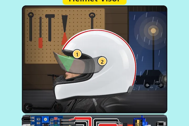 Same Arduino + servoHelmet that closes its own visorYou lower the helmet onto your head and the visor swings down by itself.
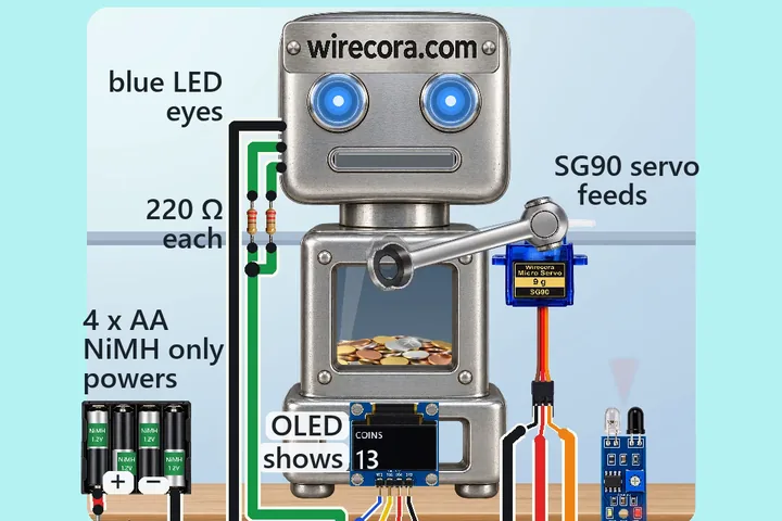 Next step: adds a displayCoin-eating robot bank with an Arduino Nano, an FC-51 IR sensor, an SG90 servo and an OLED counterSet a coin on the robot's scoop.
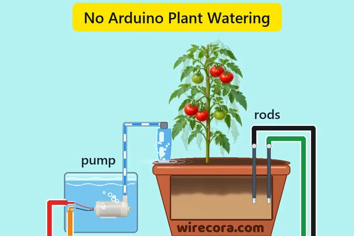 Something new: a pumpSelf-watering plant with one MOSFET (no Arduino)Two steel rods in the soil decide when the pump runs.