Helmet that closes its own visor
You lower the helmet onto your head and the visor swings down by itself. Lift the helmet off and it swings back up. It is a demo, not a certified helmet.
- 7 parts
- 5 wiring steps
- Arduino code
- 4.8 V supply
Quick answer
The short version. Every pin is in the full wiring below.What you need
- Arduino Nano
- FC-51 type IR obstacle module, in the brow liner
- SG90 servo, on the visor pivot
- 100 uF 25 V electrolytic capacitor
- SPDT slide switch
- 4 x AA battery holder with NiMH cells
- Breadboard power rail and jumper wires
How to wire it
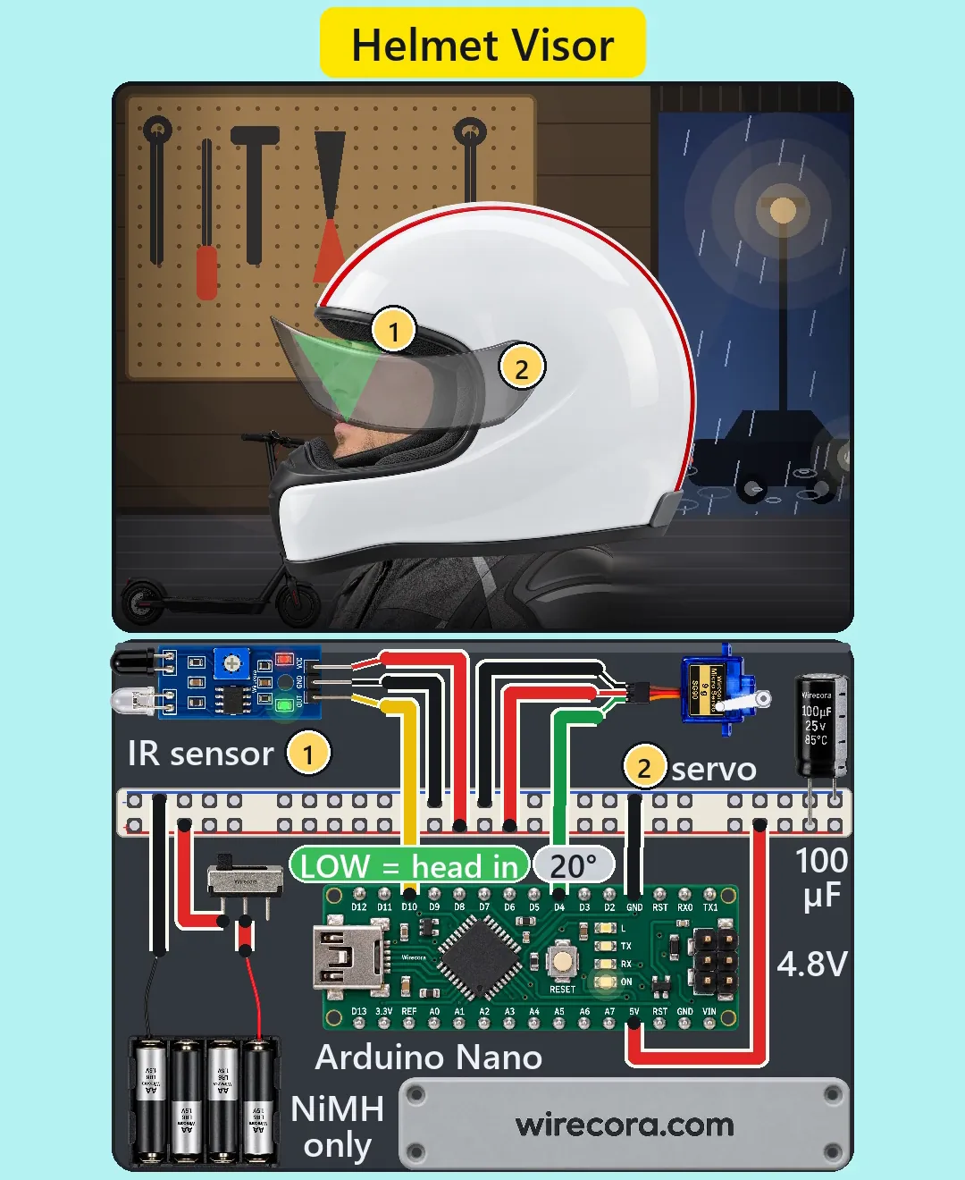
- Battery holder plus to the slide switch COM, switch A to the plus rail, and holder minus to the minus rail.
- Plus rail to the Nano's 5V pin, the IR module's VCC, the servo's red lead and the plus of the 100 uF capacitor.
- Minus rail to the Nano GND, the IR module's GND, the servo's brown lead and the capacitor's stripe.
- IR module OUT to D10.
- Servo orange lead to D4.
Before you power it: 4.8 V from NiMH cells only: four fresh alkaline cells are 6.4 V, over the Nano chip's 6.0 V limit on the 5V pin. A demo, not a certified helmet and not for the road. Use adhesive mounts only and drill nothing into the shell.
Parts list
- Arduino Nano
- FC-51 type IR obstacle module, in the brow liner
- SG90 servo, on the visor pivot
- 100 uF 25 V electrolytic capacitor
- SPDT slide switch
- 4 x AA battery holder with NiMH cells (4.8 V)
- Breadboard power rail and jumper wires (no resistor and no diode: nothing drives a coil or an LED from a pin)
Wiring, step by step
- Battery holder plus to the slide switch COM, switch A to the plus rail, and holder minus to the minus rail.
- Plus rail to the Nano's 5V pin, the IR module's VCC, the servo's red lead and the plus of the 100 uF capacitor. Nothing goes on VIN, and no USB while it runs.
- Minus rail to the Nano GND, the IR module's GND, the servo's brown lead and the capacitor's stripe.
- IR module OUT to D10.
- Servo orange lead to D4.
How it works
- The IR module looks at your forehead from the shaded brow liner. It is active low: OUT goes low when it sees you and high when it sees nothing.
- The Nano waits for 250 ms of low, then turns the servo from 100 to 20 degrees (80 degrees of visor travel) in 35 steps of 20 ms, holds 0.2 s and detaches.
- After 500 ms of high it opens the visor the same way.
- The servo lets go after every move, so you can push the visor open by hand at any time. It closes once when your head arrives and never locks.
The code: helmet_visor.ino
The Arduino code for this circuit is in the Wirecora Discord, in the channel #arduino-code (owner’s choice, 14 October 2026: the code lives where you can ask about it). It is a plain .ino file you can download there.
From the Short's own checked drawing; it needs only the Servo library that comes with the Arduino software. It was checked by simulation, not run on a real helmet. Tune the 100 and 20 degree angles to your visor.
What the video simplifies
- The camera follows the helmet, so the rider and garage move behind it. The rain, car and garage are staged.
- The sensor and servo are drawn in the panel below, with their leads to the helmet left out. The infrared cone is drawn (infrared is invisible). The electronics are drawn much larger than the helmet.
- A slip washer and a detent at the visor pivot are not drawn.
- The sensor range, currents, cell voltages and visor mass are typical values, not measured. Strong sun into the open shell can fool a plain IR sensor, so it is built for indoors and shade. A glove left inside looks like a head. The sounds are synthesised.
- The pack uses about 65 mA waiting and 0.28 A for 0.7 s per move, and up to 0.71 A for under a second if the visor is blocked. That is over this switch's 0.5 A, so use a 1 A switch in a real build.
- This was checked by simulation and datasheets, not built.
You found this by searching. Here's the whole path.
- Read how it works
- See it work
- Build it
- Show it
Thirty seconds of video shows the circuit doing its job.
4.8 V from NiMH cells only: four fresh alkaline cells are 6.4 V, over the Nano chip's 6.0 V limit on the 5V pin. A demo, not a certified helmet and not for the road. Use adhesive mounts only and drill nothing into the shell.
Built it, or stuck halfway? Post a photo in the Wirecora Discord. Questions get an answer every day.
What to build next
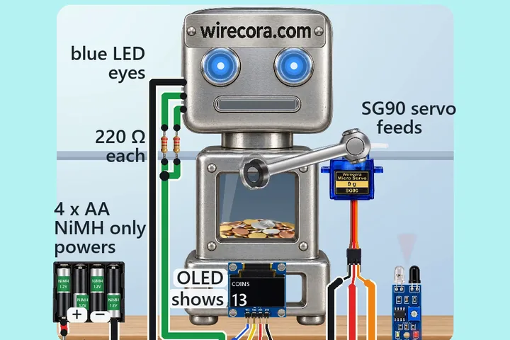 Same Arduino + servoCoin-eating robot bank with an Arduino Nano, an FC-51 IR sensor, an SG90 servo and an OLED counterSet a coin on the robot's scoop.
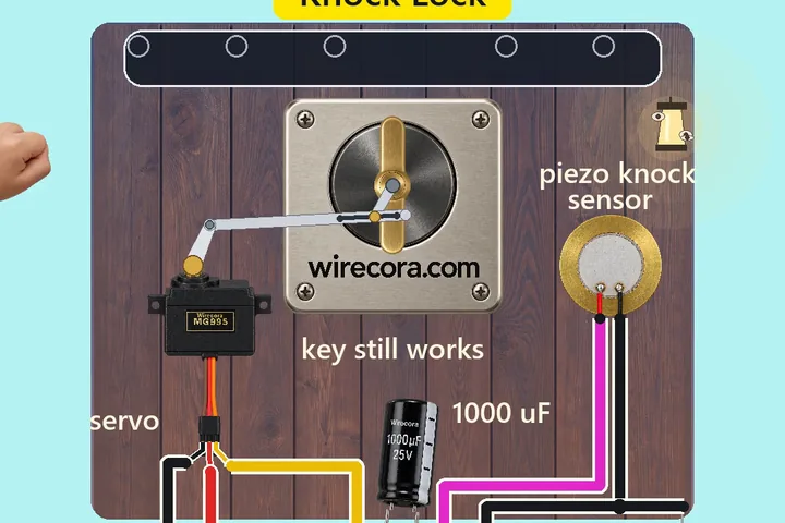 Next step: adds a buzzerSecret knock door lockKnock the secret rhythm on the door and the deadbolt turns for you.
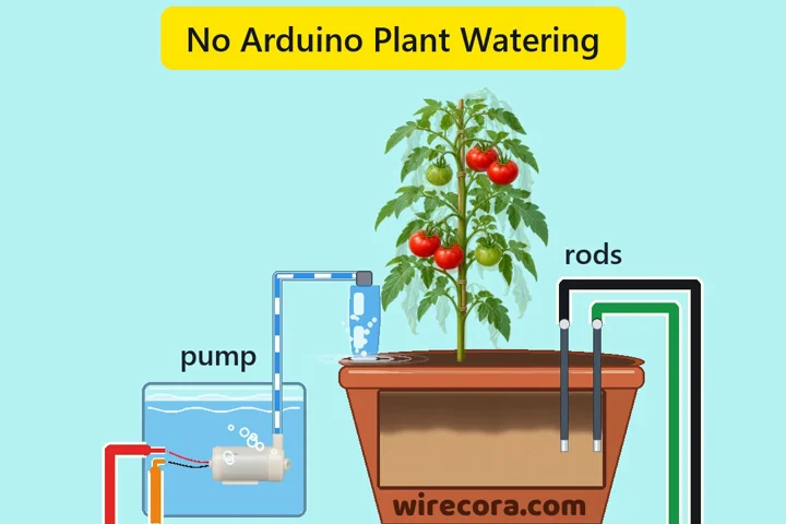 Something new: a pumpSelf-watering plant with one MOSFET (no Arduino)Two steel rods in the soil decide when the pump runs.