Secret knock door lock
Knock the secret rhythm on the door and the deadbolt turns for you. A wrong rhythm gets a red light and a small servo twitch, and the bolt stays shut. Both arms full of groceries and no hand free for the keys: the knock opens it.
- 11 parts
- 8 wiring steps
- Arduino code
- 5 V supply
Quick answer
The short version. Every pin is in the full wiring below.What you need
- Arduino Nano
- MG995 servo
- 27 mm piezo disc
- 1N4733A zener diode, 5.1 V
- 1 Mohm resistor
- 4.7 kohm resistor
- 220 ohm resistor, two of them, one for each LED
- 5 mm green LED and 5 mm red LED
- 6 mm push button
- 1000 uF 25 V electrolytic capacitor
- 5 V 2 A power supply
How to wire it
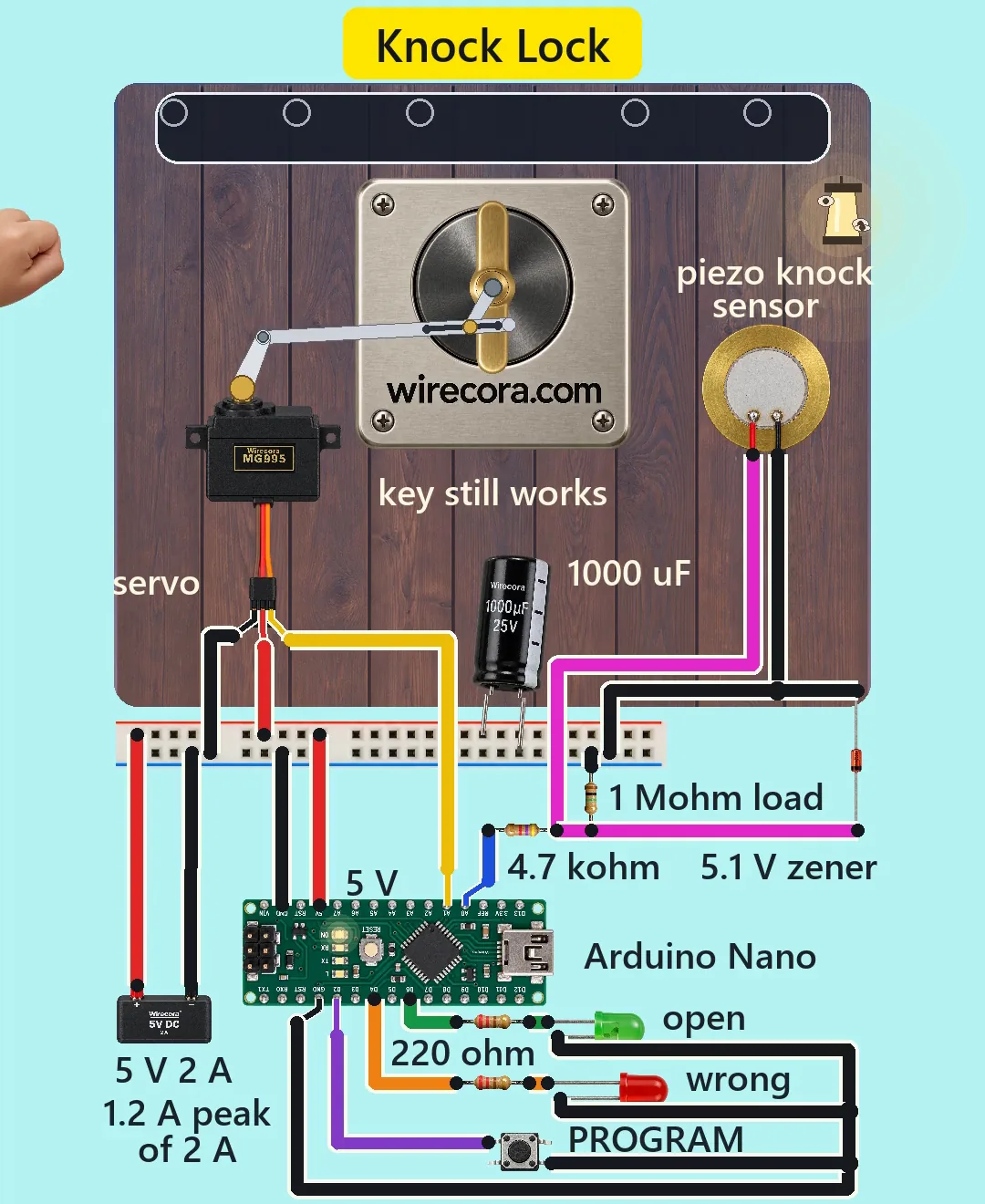
- Supply plus and minus to the breadboard power rail.
- Rail 5 V to the Nano's 5V pin, the servo's red lead and the plus of the 1000 uF capacitor.
- Every ground to the minus rail: the Nano GND, the servo's brown lead, the capacitor's stripe, the piezo's black lead and both LED cathodes.
- Piezo red lead to a node that also holds the 1 Mohm resistor to ground and the zener, its band on the node and its other end (anode) to ground.
- That same node through the 4.7 kohm resistor to A0.
- Servo orange lead to A1.
- D6 through a 220 ohm resistor to the green LED anode, and D4 through a 220 ohm resistor to the red LED anode.
- D2 to a top leg of the button and ground to the bottom leg on the other side.
Before you power it: All 5 V. Keep your key, pick gaps that are not obvious, and build it only on a door you own: anyone who hears the knock can copy it.
Parts list
- Arduino Nano
- MG995 servo (turns the deadbolt's thumb-turn a quarter turn)
- 27 mm piezo disc, taped inside the door to feel the knocks
- 1N4733A zener diode, 5.1 V
- 1 Mohm resistor (from the piezo node to ground)
- 4.7 kohm resistor (in series with A0)
- 220 ohm resistor, two of them, one for each LED
- 5 mm green LED and 5 mm red LED
- 6 mm push button (PROGRAM)
- 1000 uF 25 V electrolytic capacitor
- 5 V 2 A power supply, with one breadboard power rail
Wiring, step by step
- Supply plus and minus to the breadboard power rail.
- Rail 5 V to the Nano's 5V pin, the servo's red lead and the plus of the 1000 uF capacitor. Nothing goes on VIN.
- Every ground to the minus rail: the Nano GND, the servo's brown lead, the capacitor's stripe, the piezo's black lead and both LED cathodes.
- Piezo red lead to a node that also holds the 1 Mohm resistor to ground and the zener, its band on the node and its other end (anode) to ground.
- That same node through the 4.7 kohm resistor to A0. The zener and the 1 Mohm protect A0.
- Servo orange lead to A1.
- D6 through a 220 ohm resistor to the green LED anode, and D4 through a 220 ohm resistor to the red LED anode.
- D2 to a top leg of the button and ground to the bottom leg on the other side. The two legs on one side are the switch; the legs across the body are joined inside.
How it works
- The piezo disc turns each knock into a small voltage. The 4.7 kohm and the 5.1 V zener keep it safe for A0.
- The sketch notices A0 passing 60 and records the time of every knock until 400 ms of quiet ends the pattern.
- It compares the gaps with the rhythm it remembers: the longest gap counts as 100 and the others must match within 25, so the tempo does not matter. Five knocks are needed.
- On a match the green LED lights, the servo pushes the thumb-turn a quarter turn, returns to the middle and lets go, so the key still works. After a short wait it locks again.
- On a miss the red LED lights and the servo twitches three times. To store a new rhythm, hold the button and knock five times.
The code: knock_lock.ino
The Arduino code for this circuit is in the Wirecora Discord, in the channel #arduino-code (owner’s choice, 14 October 2026: the code lives where you can ask about it). It is a plain .ino file you can download there.
From the Short's own checked drawing; it needs only the Servo library that comes with the Arduino software. It was checked by simulation, not run on a real door. Tune HIT and the 80 ms ring-down wait to your door, and set OPEN_MS to about 4000 for a real lock.
What the video simplifies
- The door is drawn see-through, and the electronics are drawn much larger than the door and the hand. The bar over the door shows what the sketch heard, and the knock rings are drawn.
- The servo swings more slowly than a real one. The lock relocks after 0.8 s in the video; use about 4 s on a real door (OPEN_MS in the sketch).
- The servo current (about 0.5 A moving, up to about 1.2 A stalled) and the piezo capacitance are typical values, not measured. The horn, link and slot on the servo are our own concept, and the sounds are synthesised.
- This was checked by simulation and datasheets, not built.
- Anyone who hears the knock can copy it, so this is a convenience lock, not a safe.
You found this by searching. Here's the whole path.
- Read how it works
- See it work
- Build it
- Show it
Thirty seconds of video shows the circuit doing its job.
All 5 V. Keep your key, pick gaps that are not obvious, and build it only on a door you own: anyone who hears the knock can copy it.
Built it, or stuck halfway? Post a photo in the Wirecora Discord. Questions get an answer every day.
What to build next
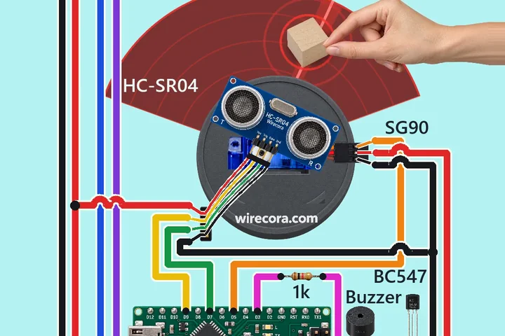 Same Arduino + servoArduino radar guard with an HC-SR04 and a servoAn ultrasonic sensor on a servo sweeps from side to side.
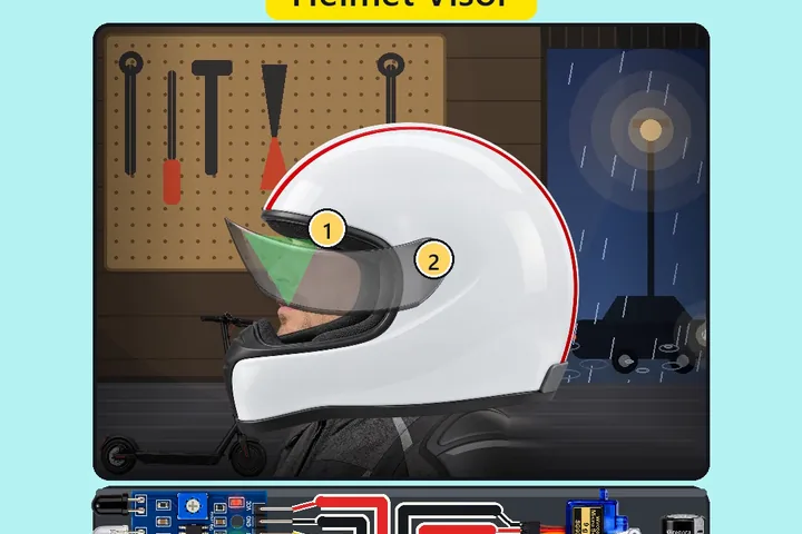 Next step: adds an IR sensorHelmet that closes its own visorYou lower the helmet onto your head and the visor swings down by itself.
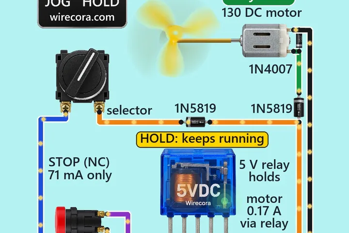 Something new: a relayJog or hold relay motor controlThe same START button gives two results.