Jog or hold relay motor control
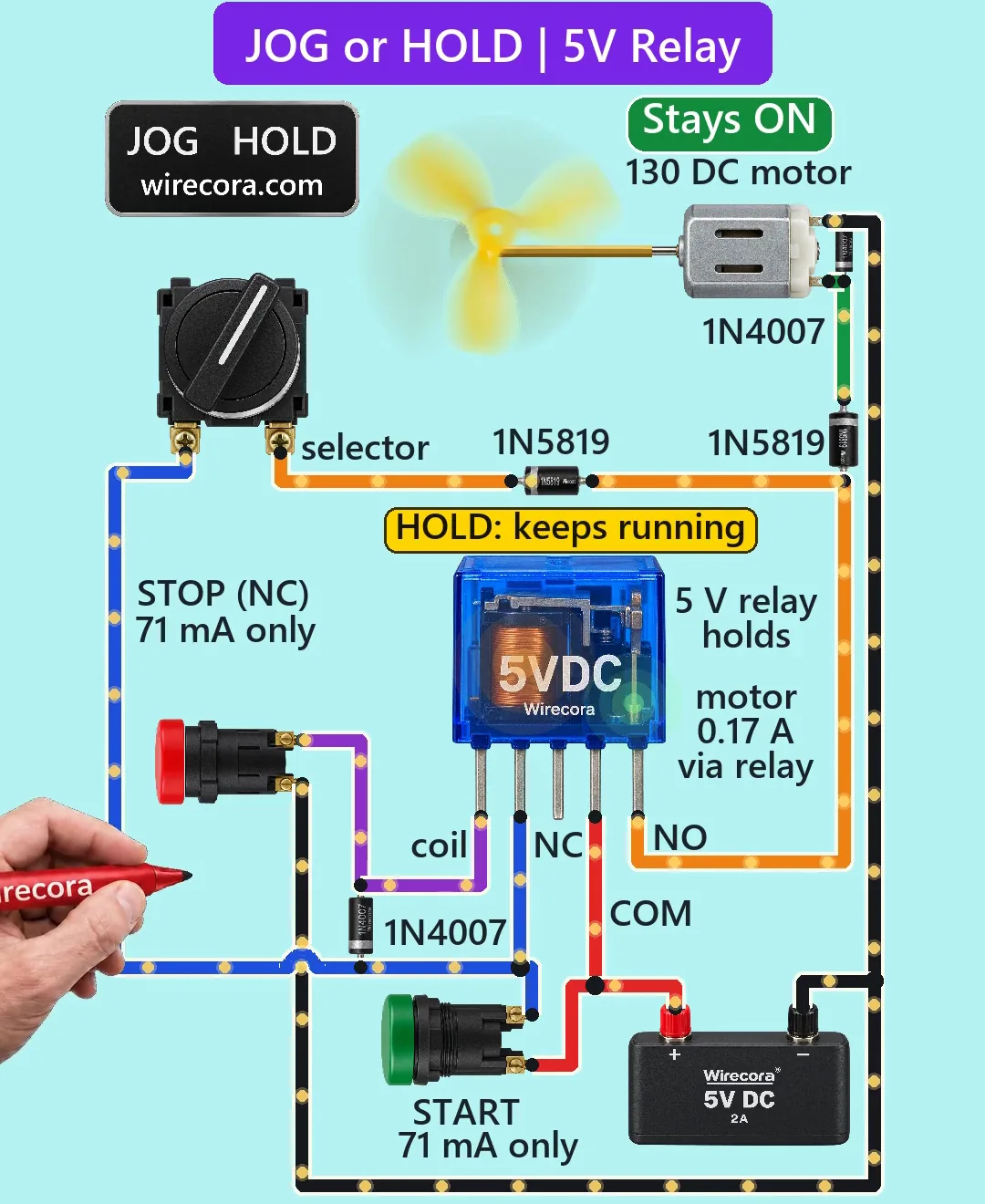
The same START button gives two results. On JOG the motor runs only while you hold START. On HOLD one tap keeps it running until you press STOP.
- 8 parts
- 6 wiring steps
- No code needed
- 5 V supply
Quick answer
The short version. Every pin is in the full wiring below.What you need
- 5 V 2 A power supply
- 5 V relay SRD-05VDC-SL-C
- 2-position stay-put selector switch with one normally open contact
- START push button, normally open
- STOP push button, normally closed
- 130 DC motor with a small propeller
- 1N4007 diode
- 1N5819 diode
How to wire it
- Supply plus to the relay's COM contact and to one side of START.
- START's other side to the relay coil plus.
- Relay coil minus through the STOP button to supply minus.
- Relay NO contact through a 1N5819 (band to the motor) to the motor.
- Relay NO contact also through the second 1N5819 (band to the selector) and the selector back to the relay coil plus.
- One 1N4007 across the coil and one across the motor, each with its band to plus.
Before you power it: All 5 V. This is not a mains wiring guide: never copy this wiring onto mains without a proper contactor and a qualified electrician.
Parts list
- 5 V 2 A power supply
- 5 V relay SRD-05VDC-SL-C (coil 70 ohm, 71 mA)
- 2-position stay-put selector switch with one normally open contact
- START push button, normally open
- STOP push button, normally closed
- 130 DC motor with a small propeller
- 1N4007 diode, two of them: one across the relay coil and one across the motor, each with its band to plus
- 1N5819 diode, two of them: one in series with the motor (band to the motor) and one in the hold path (band to the selector)
Wiring, step by step
- Supply plus to the relay's COM contact and to one side of START.
- START's other side to the relay coil plus.
- Relay coil minus through the STOP button to supply minus.
- Relay NO contact through a 1N5819 (band to the motor) to the motor. The motor's other terminal goes to supply minus.
- Relay NO contact also through the second 1N5819 (band to the selector) and the selector back to the relay coil plus. This is the hold path.
- One 1N4007 across the coil and one across the motor, each with its band to plus. The relay is drawn with its pins in a row; a real SRD has another pin pattern, so wire by pin name.
How it works
- START puts 5 V on the relay coil. The relay pulls in and its COM to NO contact runs the motor.
- In HOLD the selector is closed. The NO contact also feeds the coil back through the hold diode and the selector, so the relay keeps itself on after START is released. STOP breaks the coil's ground and lets it go.
- In JOG the selector is open, so nothing holds the relay: it drops the moment START is released.
- The buttons switch only the 71 mA coil. The motor's 0.17 A runs through the relay contact.
- The hold-path 1N5819 keeps START out of the motor feed. The motor-line 1N5819 stops the coasting motor, which acts as a generator, from keeping the relay in after a quick STOP tap.
What the video simplifies
- The propeller is drawn face-on and slowed, and the spin-up and coast-down times are chosen for the picture. The selector is drawn turning 60 degrees; a real one turns 90.
- The relay armature is not animated. The glows, current dots and labels are visual aids, and the parts are drawn larger than life.
- The motor current of 0.17 A is an assumed value. The sounds are real recordings.
- This was checked by simulation and datasheets, not built.
- Machines use JOG to inch a belt and HOLD for normal running. This page is the same logic at 5 V with one relay contact doing both jobs; the original viral circuit was a 230/400 V contactor circuit with a separate auxiliary contact.
You found this by searching. Here's the whole path.
- Read how it works
- See it work
- Build it
- Show it
Next: see it work
Thirty seconds of video shows the circuit doing its job.
Then build it
All 5 V. This is not a mains wiring guide: never copy this wiring onto mains without a proper contactor and a qualified electrician.
Then show it
Built it, or stuck halfway? Post a photo in the Wirecora Discord. Questions get an answer every day.
What to build next
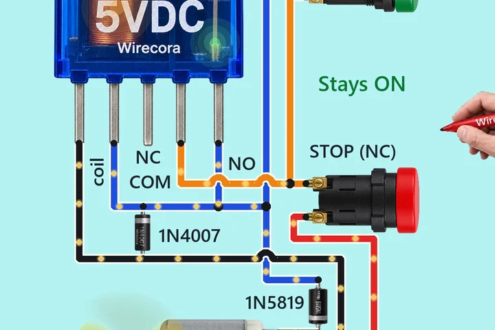 Same relay + motorStart/stop latch with one 5 V relayPress the green START button once and let go: the relay clicks in and the motor keeps spinning its propeller.
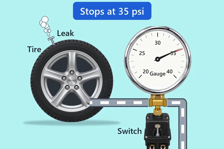 Next step: adds a pumpTyre pump that stops itself at 35 psiA pressure switch on the tyre valve tells the pump when to stop and when to start again.
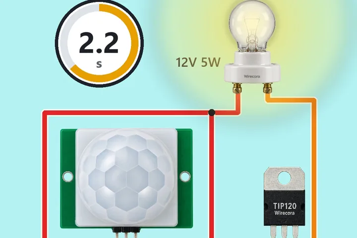 Something new: a PIR sensorPIR motion sensor lightWave a hand over the PIR sensor and a 12 V lamp turns on, counts down about 3.5 seconds, then switches itself off.