PIR motion sensor light
Wave a hand over the PIR sensor and a 12 V lamp turns on, counts down about 3.5 seconds, then switches itself off.
- 5 parts
- 4 wiring steps
- No code needed
- 12 V supply
Quick answer
The short version. Every pin is in the full wiring below.What you need
- 12 V DC power supply
- HC-SR501 PIR motion sensor module
- TIP120 Darlington transistor
- 1 kohm resistor
- 12 V 5 W lamp, about 0.42 A
How to wire it
- Supply plus to the PIR's VCC and to one lead of the lamp.
- Supply minus to the PIR's GND and to the TIP120's emitter.
- PIR OUT through the 1 kohm resistor to the TIP120's base.
- The lamp's other lead to the TIP120's collector (the metal tab is the collector).
Before you power it: 12 V DC only: no mains and no relay. No flyback diode is needed because a lamp is not inductive. The original viral version switched a 230 V mains bulb; this one is the safe 12 V version.
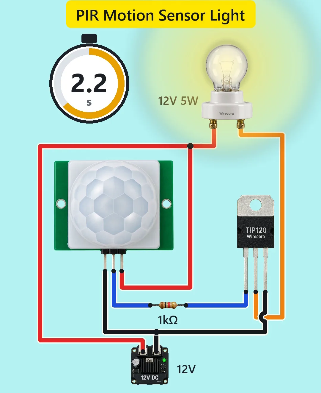
Parts list
- 12 V DC power supply
- HC-SR501 PIR motion sensor module (accepts 4.5 to 20 V)
- TIP120 Darlington transistor
- 1 kohm resistor (brown, black, red) in the base line
- 12 V 5 W lamp, about 0.42 A
Wiring, step by step
- Supply plus to the PIR's VCC and to one lead of the lamp.
- Supply minus to the PIR's GND and to the TIP120's emitter.
- PIR OUT through the 1 kohm resistor to the TIP120's base.
- The lamp's other lead to the TIP120's collector (the metal tab is the collector). Seen from the dome side with the pins at the bottom, the PIR pins are GND, OUT, VCC from left to right; the labels hide under the dome and the order is mirrored on the back. TIP120 seen from the front, legs down: base, collector, emitter.
How it works
- With nothing moving, the PIR's OUT is low, the TIP120 is off and the lamp has no path to minus.
- On motion, OUT goes to 3.3 V through the module's own 1 kohm resistor. The 1 kohm in the base line then gives about 0.9 mA of base current, about twice what the lamp needs.
- The TIP120 turns on and the 0.42 A lamp lights. The transistor warms by only about 0.3 W, so it needs no heatsink.
- The module's delay trimmer is set near its minimum, about 3.5 s, and the trigger jumper is on L (single trigger): the light goes off 3.5 s after the first detection even if you keep moving. The factory setting H keeps it on while motion continues.
- After switching off, a real HC-SR501 ignores motion for about 2.5 s.
What the video simplifies
- The 30 to 60 second warm-up of a PIR after power-on is skipped.
- The red detection rings are drawn (the module has no indicator light), and so are the lamp glow and its very fast warm-up.
- The hand passes close over the dome. A real PIR also detects motion several metres away.
- Real modules set their delay from about 1 to 3 seconds up to several minutes.
- This was checked by simulation and datasheets, not built.
You found this by searching. Here's the whole path.
- Read how it works
- See it work
- Build it
- Show it
Next: see it work
Thirty seconds of video shows the circuit doing its job.
Then build it
12 V DC only: no mains and no relay. No flyback diode is needed because a lamp is not inductive. The original viral version switched a 230 V mains bulb; this one is the safe 12 V version.
Then show it
Built it, or stuck halfway? Post a photo in the Wirecora Discord. Questions get an answer every day.
What to build next
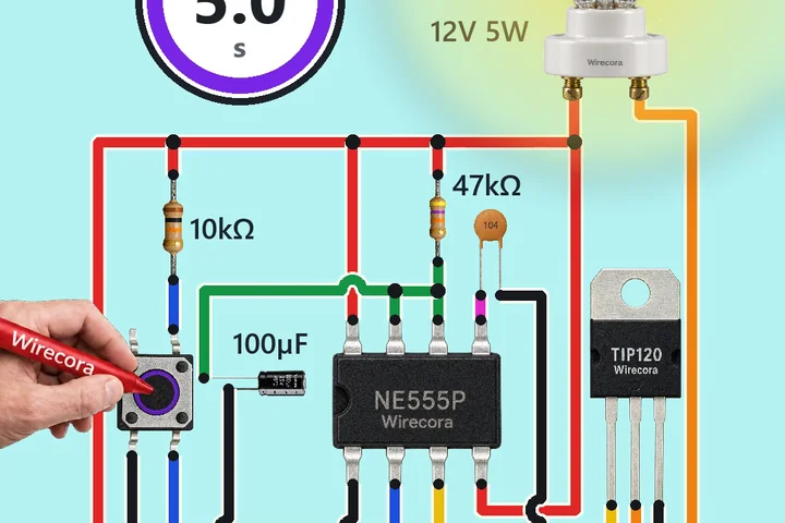 Same TIP120 + lampDelay OFF timer with a 555Press the button once: the 12 V lamp lights straight away, stays on for about 5 seconds and then switches itself off.
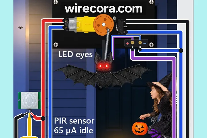 Next step: adds a motorFlapping porch bat with a motion sensor, a TIP120 and a TT gear motorTrick-or-treaters walk up to the door, a motion sensor sees them, and the big bat under the porch roof lights its red eyes and beats its wings, about two a second.
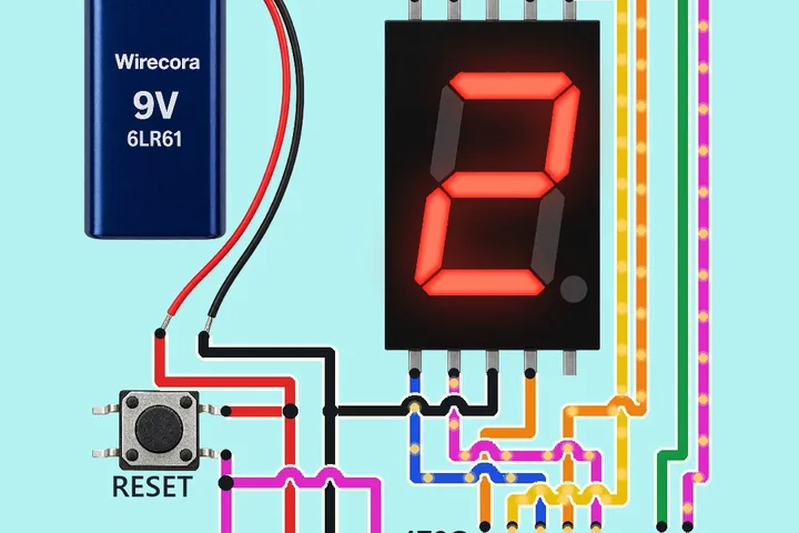 Something new: a displaySeven-segment counter, no ArduinoA 9 V battery, one CD4026 chip and a push button count up on a seven-segment display.