Seven-segment counter, no Arduino
A 9 V battery, one CD4026 chip and a push button count up on a seven-segment display. Each press of COUNT adds one (0, 1, 2, 3, 4) and RESET goes back to 0. No Arduino and no code.
- 6 parts
- 6 wiring steps
- No code needed
- 9 V supply
Quick answer
The short version. Every pin is in the full wiring below.What you need
- 9 V battery
- CD4026BE decade counter and 7-segment decoder
- Common-cathode 7-segment display, 0.56 inch
- 470 ohm resistor
- 10 kohm resistor
- 6 mm tactile push button, two of them
How to wire it
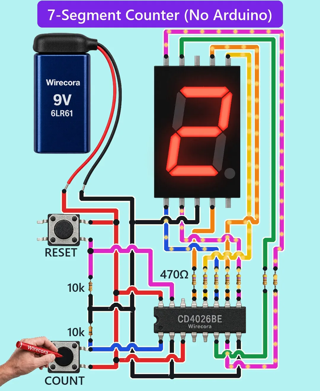
- Battery plus to the CD4026's pin 16 (+9 V) and battery minus to pin 8 (ground).
- Pin 2 (CLOCK INHIBIT) to ground and pin 3 (DISPLAY ENABLE IN) to +9 V.
- COUNT button from +9 V to pin 1 (CLOCK), with a 10 kohm resistor from pin 1 to ground so it does not float.
- RESET button from +9 V to pin 15 (RESET), with a 10 kohm resistor from pin 15 to ground.
- Pins 10, 12, 13, 9, 11, 6 and 7 are segments a to g.
- The display's centre pin to ground, because it is common cathode.
Before you power it: 9 V battery only. Keep a resistor in every segment line; without them the segments and the chip can burn out.
Parts list
- 9 V battery (6LR61) with snap
- CD4026BE decade counter and 7-segment decoder (DIP-16, works from 3 to 18 V)
- Common-cathode 7-segment display, 0.56 inch (5161AS type)
- 470 ohm resistor, seven of them, one in each segment line
- 10 kohm resistor, two of them, pulling CLOCK and RESET down to ground
- 6 mm tactile push button, two of them (COUNT and RESET)
Wiring, step by step
- Battery plus to the CD4026's pin 16 (+9 V) and battery minus to pin 8 (ground).
- Pin 2 (CLOCK INHIBIT) to ground and pin 3 (DISPLAY ENABLE IN) to +9 V.
- COUNT button from +9 V to pin 1 (CLOCK), with a 10 kohm resistor from pin 1 to ground so it does not float.
- RESET button from +9 V to pin 15 (RESET), with a 10 kohm resistor from pin 15 to ground.
- Pins 10, 12, 13, 9, 11, 6 and 7 are segments a to g. Each goes through its own 470 ohm resistor to its segment pin on the display.
- The display's centre pin to ground, because it is common cathode. Pins 4, 5 and 14 of the chip are left open. The top common pin of the display is left open because it is joined to the bottom one inside.
How it works
- The CD4026 is a decade counter and a display driver in one chip.
- Pin 1 (CLOCK) goes high when COUNT is pressed, and the chip adds one on that rising edge. The count shows on the display through the segment outputs.
- Pin 15 (RESET) goes high when RESET is pressed and clears the count to 0.
- The two 10 kohm resistors pull CLOCK and RESET down to ground, so they do not float between presses.
What the video simplifies
- The loop shows 0 to 4 only; the chip counts to 9.
- The glow is drawn much brighter than a real display at this current. With about 8 mA per lit segment assumed (the datasheet only guarantees a few mA from each output) a real display may be dimmer.
- No debounce capacitor is drawn, so a bouncy button can count twice.
- The hand, buttons and battery are drawn at different scales.
- This was checked by simulation and datasheets, not built.
You found this by searching. Here's the whole path.
- Read how it works
- See it work
- Build it
- Show it
Next: see it work
Thirty seconds of video shows the circuit doing its job.
Then build it
9 V battery only. Keep a resistor in every segment line; without them the segments and the chip can burn out.
Then show it
Built it, or stuck halfway? Post a photo in the Wirecora Discord. Questions get an answer every day.
What to build next
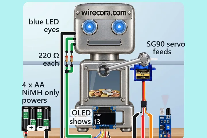 Same displayCoin-eating robot bank with an Arduino Nano, an FC-51 IR sensor, an SG90 servo and an OLED counterSet a coin on the robot's scoop.
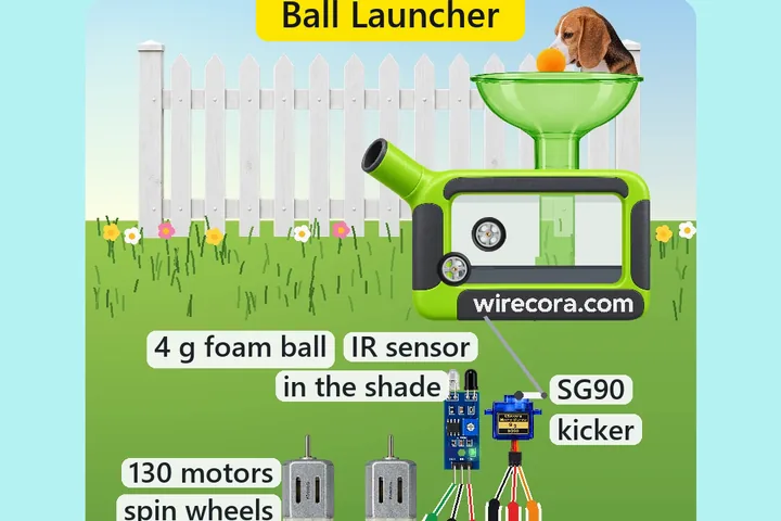 Something new: an ArduinoDog ball launcherA beagle drops a foam ball into the funnel on top and this launcher throws it back across the lawn.
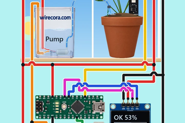 Same displaySelf-watering plant with a soil sensorWhen the soil dries out, the screen reads DRY, a small pump in the water reservoir starts and water runs through a clear hose into the pot.