Dog ball launcher
A beagle drops a foam ball into the funnel on top and this launcher throws it back across the lawn. The dog fetches it and drops it in again, with nobody holding the ball.
- 10 parts
- 7 wiring steps
- Arduino code
- 12 V supply
Quick answer
The short version. Every pin is in the full wiring below.What you need
- Arduino Nano
- FC-51 IR obstacle sensor
- SG90 servo
- 130 DC motor with a 30 mm rubber wheel
- TIP120 transistor
- 1 kohm resistor in the TIP120 base line
- 1N4007 diode, two of them, one across each motor
- 1000 uF 25 V electrolytic capacitor
- LM2596 buck module, set to 5.0 V
- 12 V 2 A power adapter with a DC barrel jack
How to wire it
- Jack plus to the LM2596's IN+, to the bottom rail and from there to the Nano's VIN pin (it takes 7 to 12 V).
- LM2596 OUT+ and OUT- feed the top rails: 5 V and ground for the IR sensor, the servo (brown GND, red 5 V) and both motors, with the 1000 uF capacitor across them.
- IR sensor OUT to D12.
- Servo orange lead to D2.
- D3 through the 1 kohm resistor to the TIP120 base, and the TIP120 emitter to ground.
- TIP120 collector to one lead of each motor and to the anode of each 1N4007.
- One motor has its leads swapped so the two wheels spin opposite ways.
Before you power it: 12 V in, 5 V on the board, about 0.5 A. Use a soft foam ball, throw it away from the dog and keep the dog behind the launcher. The sketch switches the wheels off 1 s after a trip whatever happens, so a jam cannot cook the motors. Always watch your dog.
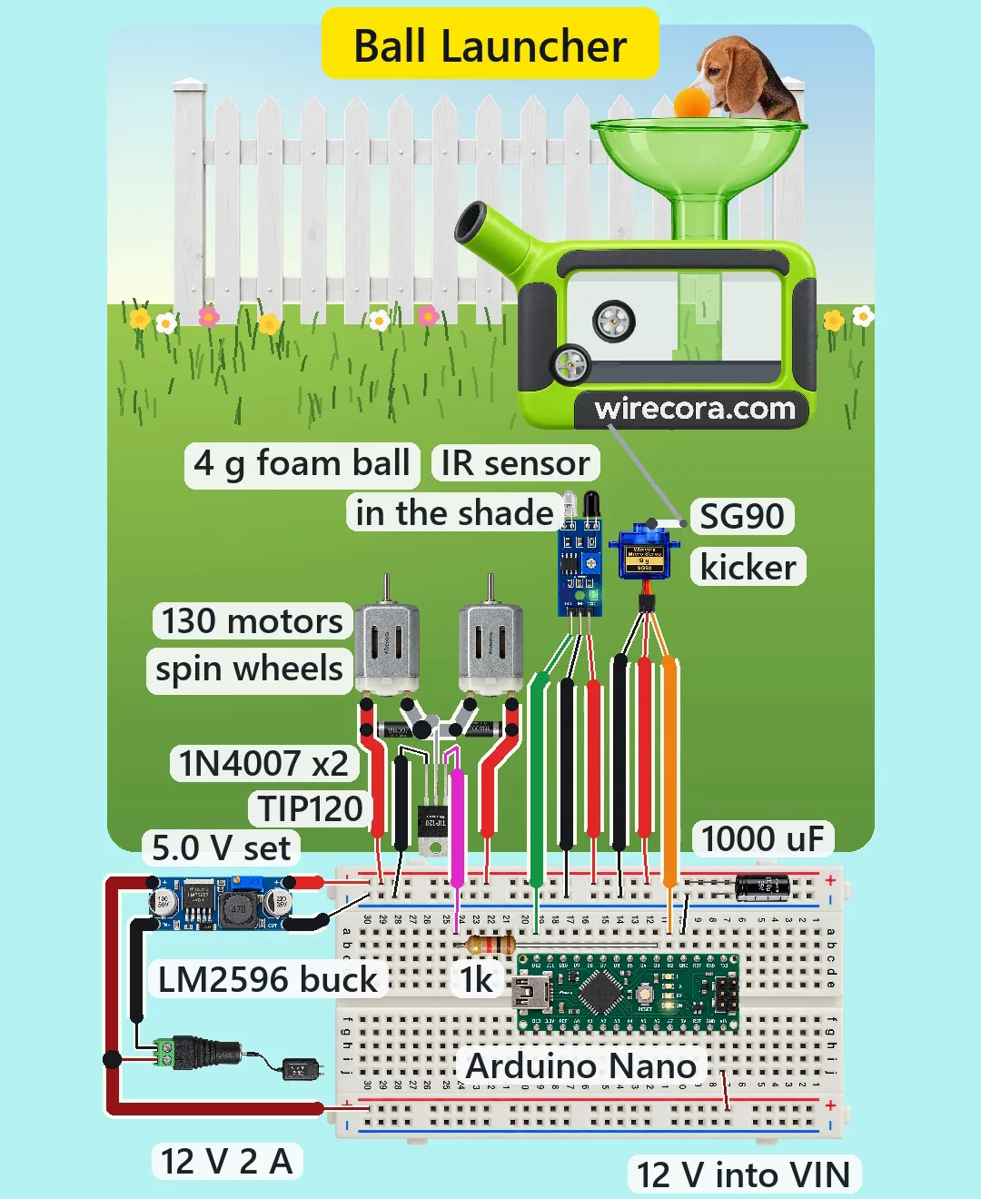
Parts list
- Arduino Nano
- FC-51 IR obstacle sensor
- SG90 servo (the kicker)
- 130 DC motor with a 30 mm rubber wheel, two of them
- TIP120 transistor
- 1 kohm resistor in the TIP120 base line
- 1N4007 diode, two of them, one across each motor
- 1000 uF 25 V electrolytic capacitor
- LM2596 buck module, set to 5.0 V
- 12 V 2 A power adapter with a DC barrel jack, and a half breadboard
Wiring, step by step
- Jack plus to the LM2596's IN+, to the bottom rail and from there to the Nano's VIN pin (it takes 7 to 12 V). Jack minus to IN-.
- LM2596 OUT+ and OUT- feed the top rails: 5 V and ground for the IR sensor, the servo (brown GND, red 5 V) and both motors, with the 1000 uF capacitor across them. The Nano's 5V pin stays empty.
- IR sensor OUT to D12.
- Servo orange lead to D2.
- D3 through the 1 kohm resistor to the TIP120 base, and the TIP120 emitter to ground.
- TIP120 collector to one lead of each motor and to the anode of each 1N4007. The 1N4007 bands go to 5 V.
- One motor has its leads swapped so the two wheels spin opposite ways.
How it works
- The infrared obstacle sensor under the tray sees the ball and its output goes low.
- The Nano spins the two rubber wheels for about 0.4 s. The whir warns the dog.
- Then the SG90 kicks the ball into the gap between the wheels, which turn opposite ways and fling it out. The barrel points up, so the servo has to push the ball in.
- The wheels stop and the Nano rests 2 s. After 10 throws it rests 5 minutes.
The code: ball_launcher.ino
The Arduino code for this circuit is in the Wirecora Discord, in the channel #arduino-code (owner’s choice, 14 October 2026: the code lives where you can ask about it). It is a plain .ino file you can download there.
From the Short's own checked drawing; it needs only the Servo library that comes with the Arduino software. It was checked by simulation, not run on a real launcher. Tune the kick angles (10 and 100) and the 400 ms wheel spin-up to your build.
What the video simplifies
- The throw is drawn shorter and the dog's run is staged. The ball is drawn small in the housing and large in flight, bigger than the dog; launcher, dog and electronics are at different scales.
- The IR sensor and servo are drawn below the open housing so their pins can be seen. In a real build they sit under the tray inside the housing, in the shade: direct sun blinds this IR module.
- The funnel and barrel are drawn narrower than a 4 cm ball needs, and the chute and kicker linkage are simplified.
- The wheel inertia, launch speed (about 4.3 m/s, flying about 2.1 m with no air drag) and the motor and servo currents are typical values. The motors run at about 4.1 V, a little under their 4.5 V minimum, and spin slower. The sounds are synthesised.
- This was checked by simulation and datasheets, not built.
You found this by searching. Here's the whole path.
- Read how it works
- See it work
- Build it
- Show it
Thirty seconds of video shows the circuit doing its job.
12 V in, 5 V on the board, about 0.5 A. Use a soft foam ball, throw it away from the dog and keep the dog behind the launcher. The sketch switches the wheels off 1 s after a trip whatever happens, so a jam cannot cook the motors. Always watch your dog.
Built it, or stuck halfway? Post a photo in the Wirecora Discord. Questions get an answer every day.
What to build next
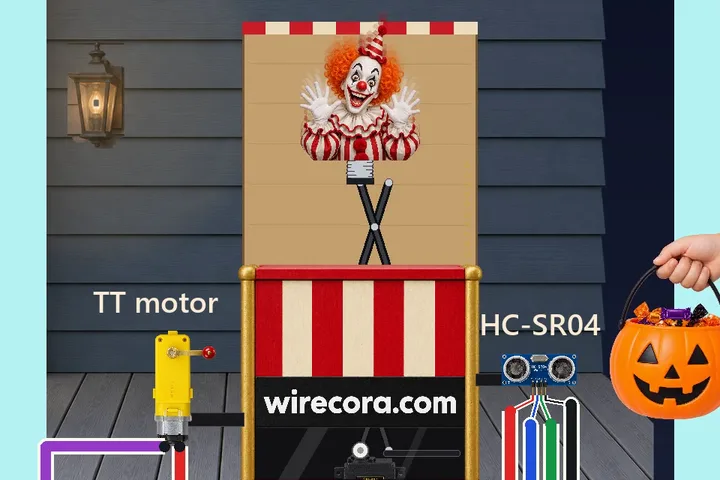 Same Arduino + servoPorch jack-in-the-box with an Arduino Nano, an HC-SR04, an MG995 servo and a TT gear motorHold your trick-or-treat pail out to the box.
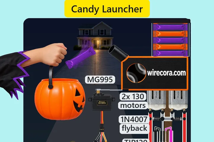 Next step: adds an ultrasonic sensorDriveway candy launcher with an HC-SR04, two flywheels, a servo and an Arduino NanoA trick-or-treater at the curb holds up a bucket.
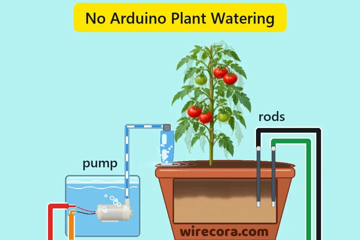 Something new: a pumpSelf-watering plant with one MOSFET (no Arduino)Two steel rods in the soil decide when the pump runs.