Self-watering plant with one MOSFET (no Arduino)
Two steel rods in the soil decide when the pump runs. Wet soil keeps the MOSFET off and the pump rests. When the soil dries, the MOSFET turns on and the pump waters the pot. When the soil is wet again, the pump stops.
- 8 parts
- 4 wiring steps
- No code needed
- 6 V supply
Quick answer
The short version. Every pin is in the full wiring below.What you need
- 4 x AA battery holder
- IRFZ44N MOSFET
- 100 kohm resistor
- 1N4007 diode
- 5 V mini submersible pump
- Two stainless steel rods with insulating sleeves and bare tips
- Clear tube from the pump to the pot
- A water tub lower than the tube outlet
How to wire it
- Battery plus to the pump's red lead, to one end of the 100 kohm resistor and to the band (cathode) of the 1N4007.
- The pump's black lead to the MOSFET drain (middle pin) and to the anode of the 1N4007.
- The other end of the 100 kohm resistor to the MOSFET gate and to one soil rod.
- The other soil rod, the MOSFET source and battery minus all go to ground.
Before you power it: Low voltage (6 V). Water and electricity: keep the battery holder and the wiring dry, and run the pump leads over the tub rim. A short across fresh AA cells gets hot, so add a fuse. Do not leave the pump to run dry.
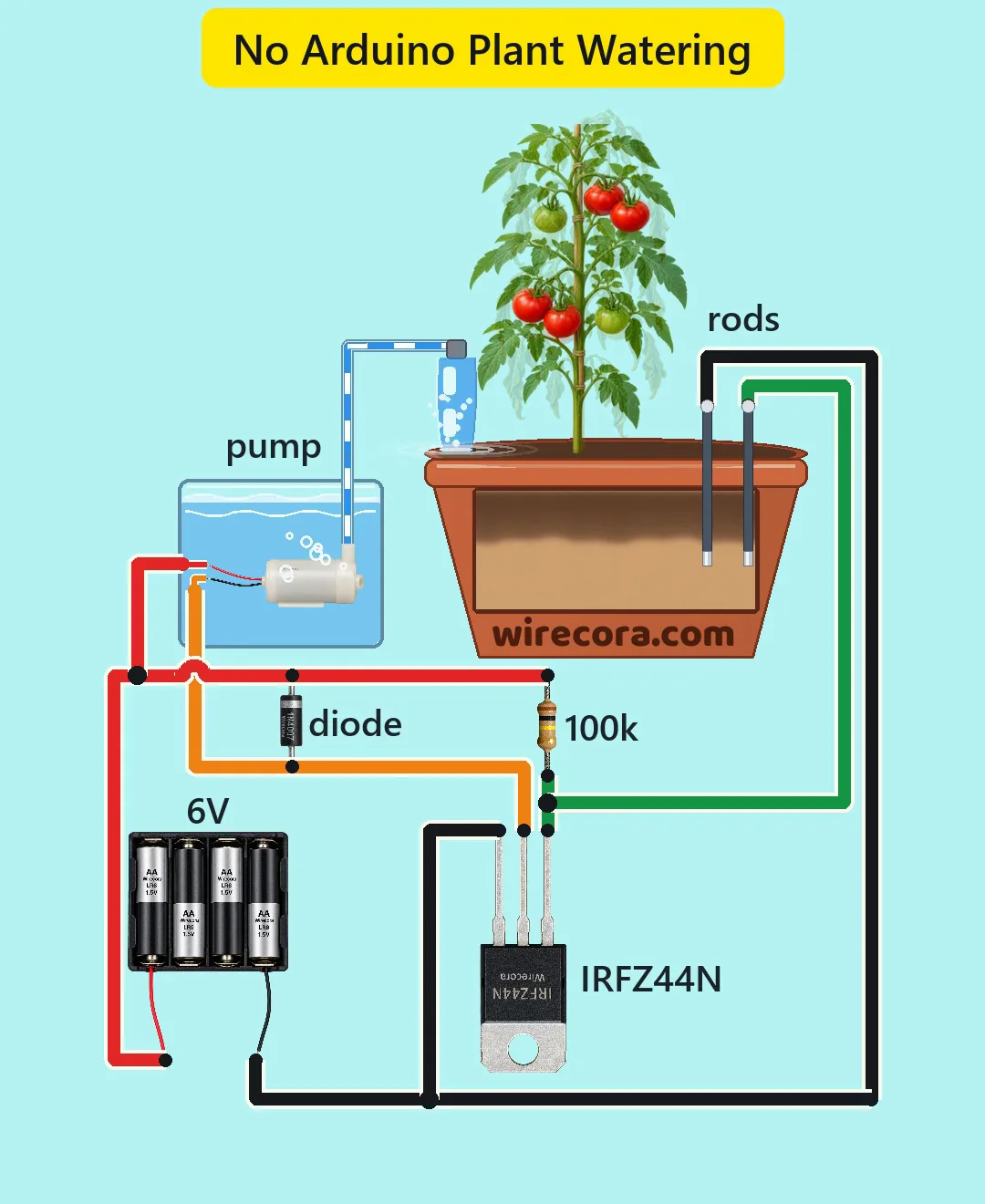
Parts list
- 4 x AA battery holder (about 6 V, 6.4 V when the cells are new)
- IRFZ44N MOSFET (pins G, D, S from the left, front view; the metal tab is the drain)
- 100 kohm resistor
- 1N4007 diode
- 5 V mini submersible pump (3 to 6 V, about 0.2 to 0.3 A)
- Two stainless steel rods with insulating sleeves and bare tips
- Clear tube from the pump to the pot
- A water tub lower than the tube outlet, so the water cannot siphon
Wiring, step by step
- Battery plus to the pump's red lead, to one end of the 100 kohm resistor and to the band (cathode) of the 1N4007.
- The pump's black lead to the MOSFET drain (middle pin) and to the anode of the 1N4007. The diode sits across the pump.
- The other end of the 100 kohm resistor to the MOSFET gate and to one soil rod.
- The other soil rod, the MOSFET source and battery minus all go to ground.
How it works
- The 100 kohm resistor pulls the gate up toward the battery. The soil between the rods pulls the gate back down.
- Damp soil has low resistance (assumed about 20 kohm). The gate sits near 1 V, so the MOSFET stays off and the pump rests.
- As the soil dries, its resistance climbs (assumed about 1 Mohm for dry). The gate rises past about 3 to 4 V. This differs from part to part.
- The MOSFET turns on and the pump runs. Water wets the soil, the resistance falls, the gate drops and the pump stops.
- When the pump stops, its motor kicks. The 1N4007 catches that spike. In a simulation the drain reaches 7 V with the diode and 56 V without it.
What the video simplifies
- Days of drying pass in about 3.5 s. The wet front and the plant lifting and sagging are sped up too.
- The soil numbers (about 20 kohm wet, about 1 Mohm dry) are assumed, not measured. Every soil and rod pair reads differently. Set the 100 kohm by trial.
- The real circuit has no snap action. On slow drying the pump fades in over minutes to hours, humming or trickling first. This uses battery and warms the MOSFET.
- Fresh AA cells give 6.4 V, a little above the pump's 3 to 6 V range. The pack falls to 6 V within minutes.
- The wilted look is generated art faded into the upright plant. The wet front is drawn flat across the pot. The stream is thicker than the tube could give.
- The parts are drawn larger than the pot. The pump leads pass through the tub wall in the picture; run them over the rim. No fuse is drawn; add one in a real build.
- A broken rod wire or a badly corroded rod keeps the pump running until the tub is empty. An empty tub runs the pump dry. Nothing stops it.
- DC on the rods corrodes them slowly. Use stainless steel and clean them. Higher bare tips mean less water before it stops.
- This circuit was checked by simulation and datasheets only. It was not built.
You found this by searching. Here's the whole path.
- Read how it works
- See it work
- Build it
- Show it
Thirty seconds of video shows the circuit doing its job.
Low voltage (6 V). Water and electricity: keep the battery holder and the wiring dry, and run the pump leads over the tub rim. A short across fresh AA cells gets hot, so add a fuse. Do not leave the pump to run dry.
Built it, or stuck halfway? Post a photo in the Wirecora Discord. Questions get an answer every day.
What to build next
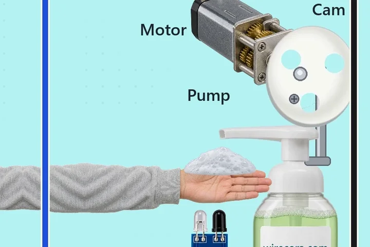 Same pump + MOSFETTouchless foam soap dispenserYou hold a hand under the nozzle.
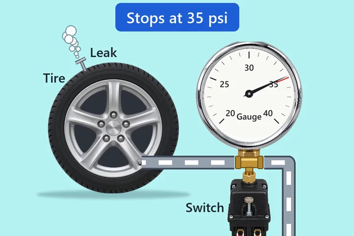 Next step: adds a relayTyre pump that stops itself at 35 psiA pressure switch on the tyre valve tells the pump when to stop and when to start again.
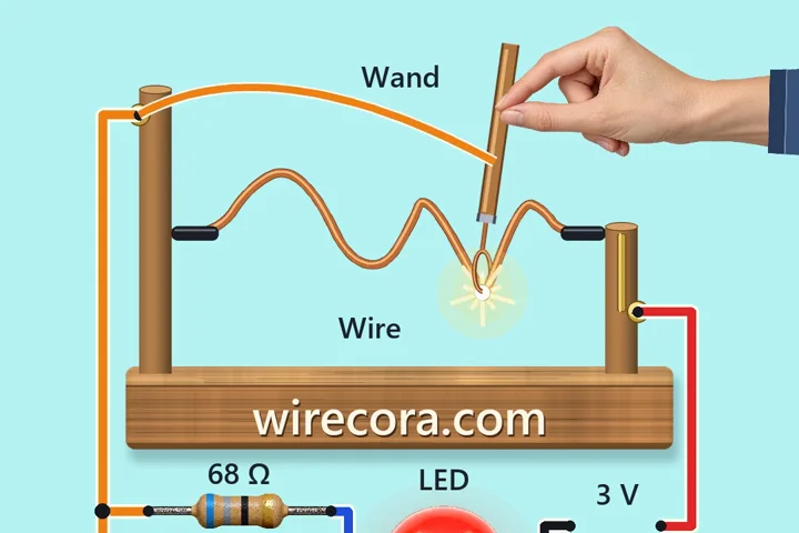 Something new: a buzzerBuzz wire game with an LED and a buzzerThe whole game is one switch: the loop and the bent wire.