Tyre pump that stops itself at 35 psi
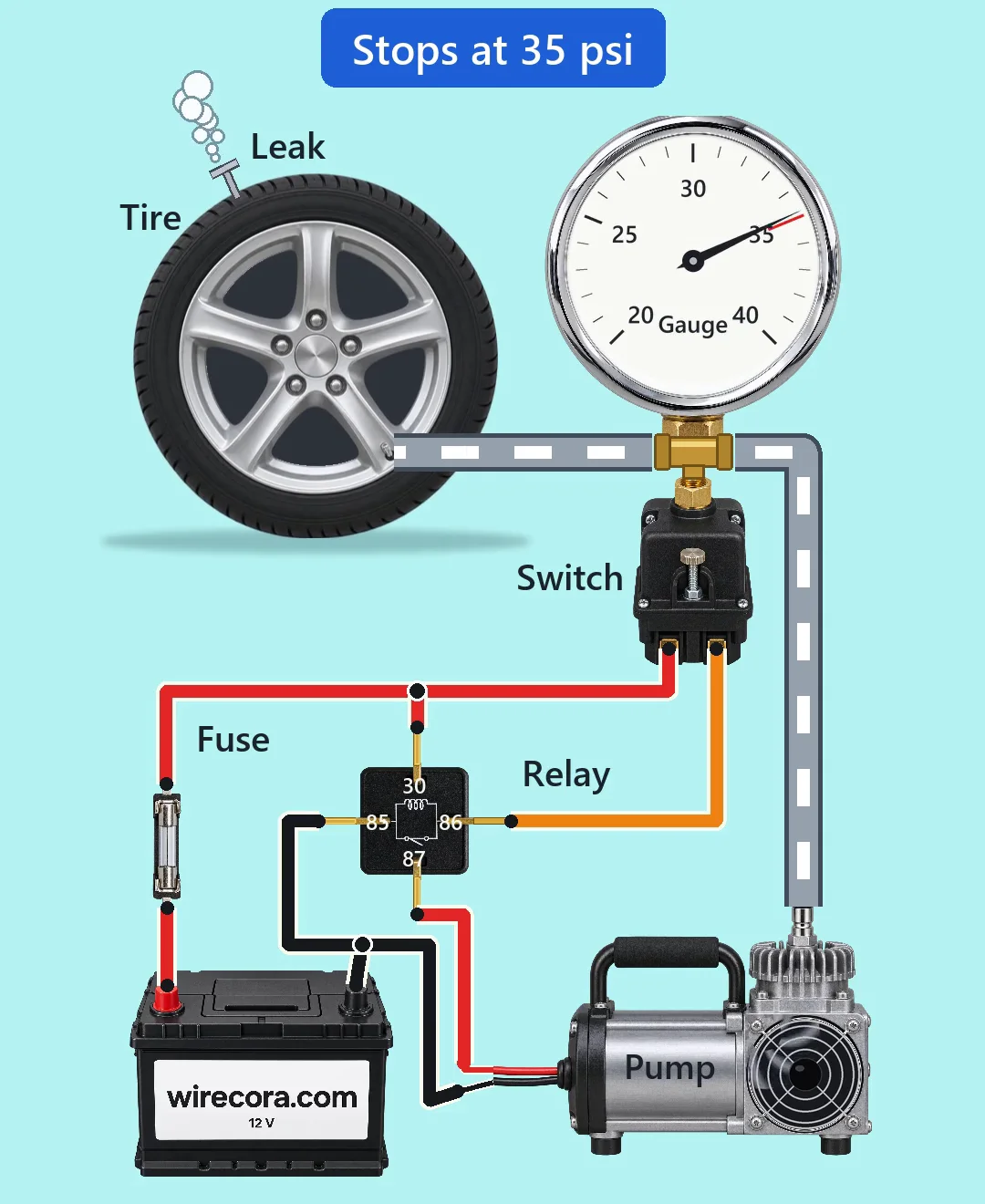
A pressure switch on the tyre valve tells the pump when to stop and when to start again. The pump stops at 35 psi (2.4 bar). If a slow leak lets the pressure fall, the pump starts again at the switch's lower point (assumed 30 psi). There is no chip and no screen.
- 7 parts
- 5 wiring steps
- No code needed
- 12 V supply
Quick answer
The short version. Every pin is in the full wiring below.What you need
- 12 V car battery
- In-line blade fuse in a holder next to the battery
- Adjustable air pressure switch
- 12 V 40 A car relay with a built-in diode and a coil of 60 ohm or more
- 12 V tyre compressor
- Heavy wire
- If your relay has no diode: a 1N4007 across pins 86 and 85
How to wire it
- Battery plus to the fuse, and the fuse to relay pin 30 and to one terminal of the pressure switch.
- The other terminal of the switch to relay pin 86 (coil plus).
- Relay pin 87 to the pump's red lead.
- Battery minus, relay pin 85 and the pump's black lead all join.
- Fit the switch on the tyre valve line, with the gauge, so it reads the tyre pressure.
Before you power it: A car battery can push hundreds of amps into a short, so the fuse goes right next to the battery. Use the pressure on your door sticker and never more than the tyre's sidewall maximum. If the switch sticks closed, the pump keeps going, so stay next to it the whole time. Keep to the compressor's duty cycle (one listing: about 25 min at 30 psi). This only tops up a leaking tyre. Fix the leak.
Parts list
- 12 V car battery
- In-line blade fuse in a holder next to the battery (the rating your compressor's maker names; 25 A in one manual, 20 A in a retailer listing)
- Adjustable air pressure switch, normally closed, set to open at 35 psi (the QPM11 type has contacts rated about 0.5 A, from seller listings)
- 12 V 40 A car relay with a built-in diode and a coil of 60 ohm or more
- 12 V tyre compressor (about 20 A)
- Heavy wire (10 to 12 AWG class) for the pump path, thin wire for the coil
- If your relay has no diode: a 1N4007 across pins 86 and 85, stripe to 86
Wiring, step by step
- Battery plus to the fuse, and the fuse to relay pin 30 and to one terminal of the pressure switch.
- The other terminal of the switch to relay pin 86 (coil plus).
- Relay pin 87 to the pump's red lead.
- Battery minus, relay pin 85 and the pump's black lead all join.
- Fit the switch on the tyre valve line, with the gauge, so it reads the tyre pressure.
How it works
- Below the set pressure the switch is closed. It feeds the relay coil (pins 86 and 85), so the relay joins pins 30 and 87 and the pump gets the battery.
- At 35 psi the switch opens. The coil drops out, the relay opens and the pump stops.
- The switch only carries the coil's small current, about half an amp at most. The relay carries the pump's 20 A.
- With a slow leak, the pressure falls. At the switch's lower point the switch closes again and the pump restarts.
- The fuse sits in the only feed, so it protects both the coil leg and the pump leg.
What the video simplifies
- Pressure and leak are sped up a lot. A real inflator adds about 0.3 psi per second and a real slow leak is far slower and invisible. The white puffs at the nail are drawn.
- The tyre's sag is exaggerated. A real tyre changes a few millimetres between 30 and 35 psi.
- The gauge is a zoomed 20 to 40 psi dial.
- The switch, relay and fuse are drawn several times larger than real next to a full-size tyre. The fuse is a symbol with no rating.
- The switch's lower point (30 psi) is assumed. No maker datasheet gave the differential.
- The relay coil current is not confirmed on a datasheet. Pick a relay whose coil is 60 ohm or more, so the coil stays under the switch's 0.5 A.
- Every wire is drawn at one thickness. A real build needs thick wire for the pump and thin wire for the coil.
- The reading at the valve runs a little high while air flows. Check with your own gauge.
- This circuit was worked out from retailer listings and the relay wiring. The pump rig was not built, and it is not tyre safety advice.
You found this by searching. Here's the whole path.
- Read how it works
- See it work
- Build it
- Show it
Thirty seconds of video shows the circuit doing its job.
A car battery can push hundreds of amps into a short, so the fuse goes right next to the battery. Use the pressure on your door sticker and never more than the tyre's sidewall maximum. If the switch sticks closed, the pump keeps going, so stay next to it the whole time. Keep to the compressor's duty cycle (one listing: about 25 min at 30 psi). This only tops up a leaking tyre. Fix the leak.
Built it, or stuck halfway? Post a photo in the Wirecora Discord. Questions get an answer every day.
What to build next
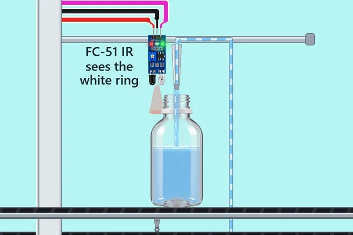 Same relay + pumpArduino bottle filler with one relayA belt brings an empty bottle.
 Next step: adds a buzzerParcel alarm that keeps goingLift the parcel and a siren sounds with red and blue strobe flashes.
 Something new: a buzzerBuzz wire game with an LED and a buzzerThe whole game is one switch: the loop and the bent wire.